SIOS SANless clusters

SIOS SANless clusters High-availability Machine Learning monitoring

  • Home
  • Products
    • SIOS DataKeeper for Windows
    • SIOS Protection Suite for Linux
  • News and Events
  • Clustering Simplified
  • Success Stories
  • Contact Us
  • English
  • 中文 (中国)
  • 中文 (台灣)
  • 한국어
  • Bahasa Indonesia
  • ไทย

Do You Know How Much Bandwidth To Support Real-Time Replication?

December 5, 2018 by Jason Aw Leave a Comment

Bandwidth To Support Real-Time Replication

How Much Bandwidth To Support Real-Time Replication?

When you want to replicate data across multi-site or wide area network (WAN) configurations, you first need to answer one important question: Is there sufficient bandwidth to successfully replicate the partition and keep the mirror in the mirroring state as the source partition is updated throughout the day? Keeping the mirror in the mirroring state is crucial. A partition switchover is allowed only when the mirror is in the mirroring state.

Therefore, an important early step to figure out how much Bandwidth To Support Real-Time Replication is determining your network bandwidth requirements. How can you measure the rate of change—the value that indicates the amount of network bandwidth needed to replicate your data?

Establish Basic Rate of Change

First, use these commands to determine the basic daily rate of change for the files or partitions that you want to mirror; for example, to measure the amount of data written in a day for /dev/sda3, run this command at the beginning of the day:

MB_START=`awk ‘/sda3 / { print $10 / 2 / 1024 }’ /proc/diskstats`

Wait for 24 hours, then run this command:

MB_END=`awk ‘/sda3 / { print $10 / 2 / 1024 }’ /proc/diskstats`

The daily rate of change, in megabytes, is then MB_END – MB_START.

The amounts of data that you can push through various network connections are as follows:

  • For T1 (1.5Mbps): 14,000 MB/day (14 GB)
  • For T3 (45Mbps): 410,000 MB/day (410 GB)
  • For Gigabit (1Gbps): 5,000,000 MB/day (5 TB)

Establish Detailed Rate of Change

What’s next to calculate Bandwidth To Support Real-Time Replication? You’ll need to measure detailed rate of change. The best way to collect this data is to log disk write activity for some period (e.g., one day) to determine the peak disk write periods. To do so, create a cron job that will log the timestamp of the system followed by a dump of /proc/diskstats. For example, to collect disk stats every 2 minutes, add this link to /etc/crontab:

*/2 * * * * root ( date ; cat /proc/diskstats ) >> /path_to/filename.txt

Wait for the determined period (e.g., one day, one week), then disable the cron job and save the resulting /proc/diskstats output file in a safe location.

Analyze and Graph Detailed Rate of Change Data

Next you should analyze the detailed rate of change data. You can use the roc-calc-diskstats utility for this task. This utility takes the /proc/diskstats output file and calculates the rate of change of the disks in the dataset. To run the utility, use this command:

# ./roc-calc-diskstats <interval> <start_time> <diskstats-data-file> [dev-list]

For example, the following dumps a summary (with per-disk peak I/O information) to the output file results.txt:

# ./roc-calc-diskstats 2m “Jul 22 16:04:01” /root/diskstats.txt sdb1,sdb2,sdc1 > results.txt

Here are sample results from the results.txt file:

Sample start time: Tue Jul 12 23:44:01 2011

Sample end time: Wed Jul 13 23:58:01 2011

Sample interval: 120s #Samples: 727 Sample length: 87240s

(Raw times from file: Tue Jul 12 23:44:01 EST 2011, Wed Jul 13 23:58:01 EST 2011)

Rate of change for devices dm-31, dm-32, dm-33, dm-4, dm-5, total

dm-31 peak:0.0 B/s (0.0 b/s) (@ Tue Jul 12 23:44:01 2011) average:0.0 B/s (0.0 b/s)

dm-32 peak:398.7 KB/s (3.1 Mb/s) (@ Wed Jul 13 19:28:01 2011) average:19.5 KB/s (156.2 Kb/s)

dm-33 peak:814.9 KB/s (6.4 Mb/s) (@ Wed Jul 13 23:58:01 2011) average:11.6 KB/s (92.9 Kb/s)

dm-4 peak:185.6 KB/s (1.4 Mb/s) (@ Wed Jul 13 15:18:01 2011) average:25.7 KB/s (205.3 Kb/s)

dm-5 peak:2.7 MB/s (21.8 Mb/s) (@ Wed Jul 13 10:18:01 2011) average:293.0 KB/s (2.3 Mb/s)

total peak:2.8 MB/s (22.5 Mb/s) (@ Wed Jul 13 10:18:01 2011) average:349.8 KB/s (2.7 Mb/s)

To help you understand your specific bandwidth needs over time, you can graph the detailed rate of change data. The following dumps graph data to results.csv (as well as dumping the summary to results.txt):

# export OUTPUT_CSV=1

# ./roc-calc-diskstats 2m “Jul 22 16:04:01” /root/diskstats.txt sdb1,sdb2,sdc1 2> results.csv > results.txt

SIOS has created a template spreadsheet, diskstats-template.xlsx, which contains sample data that you can overwrite with your data from roc-calc-diskstats. The following series of images show the process of using the spreadsheet.

  1. Open results.csv, and select all rows, including the total column.

Bandwidth To Support Real-Time Replication

  1. Open diskstats-template.xlsx, select the diskstats.csv worksheet.

2-diskstats-worksheet

  1. In cell 1-A, right-click and select Insert Copied Cells.
  2. Adjust the bandwidth value in the cell towards the bottom left of the worksheet (as marked in the following figure) to reflect the amount of bandwidth (in megabits per second) that you have allocated for replication. The cells to the right are automatically converted to bytes per second to match the collected raw data.

3-extend-existing-bandwidth_536x96

  1. Take note of the following row and column numbers:
    • Total (row 6 in the following figure)
    • Bandwidth (row 9 in the following figure)
    • Last datapoint (column R in the following figure)

4-note-row-colums_535x86

  1. Select the bandwidth vs ROC worksheet.

5-bandwidth-worksheet

  1. Right-click the graph and choose Select Data.
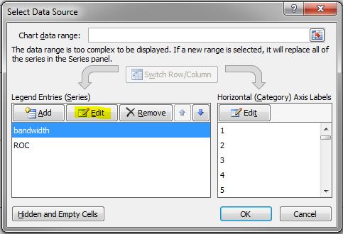
  2. In the Select Data Source dialog box, choose bandwidth in the Legend Entries (Series) list, and then click Edit.

6-edit-bandwidth

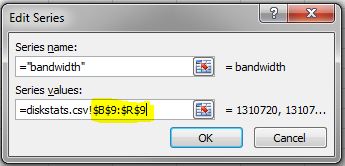
  1. In the Edit Series dialog box, use the following syntax in the Series values field: =diskstats.csv!$B$<row>:$<final_column>$<row> The following figure shows the series values for the spread B9 to R9.

7-bandwidth-values

  1. Click OK to close the Edit Series box.
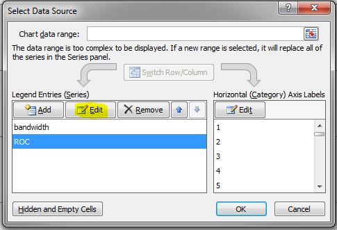
  2. In the Select Data Source box, choose ROC in the Legend Entries (Series) list, and then click Edit.

8-edit-roc

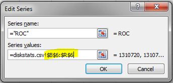
  1. In the Edit Series dialog box, use the following syntax in the Series values field: =diskstats.csv!$B$<row>:$<final_column>$<row> The following figure shows the series values for the spread B6 to R6.

9-roc-values

  1. Click OK to close the Edit Series box, then click OK to close the Select Data Source box.

The Bandwidth vs ROC graph updates. Analyze your results to determine whether you have sufficient bandwidth to support data replication.

Next Steps

If your Rate of Change exceeds your available bandwidth, you will need to consider some of the following points to ensure your replication solution performs optimally:

  • Enable compression in your replication solution or in the network hardware. (DataKeeper for Linux, which is part of the SteelEye Protection Suite for Linux, supports this type of compression.)
  • Create a local, non-replicated storage repository for temporary data and swap files that don’t need to be replicated.
  • Reduce the amount of data being replicated.
  • Increase your network capacity.

For quick how-tos like figuring Bandwidth To Support Real-Time Replication, read our blog

Reproduced with permission from Linuxclustering

Filed Under: Clustering Simplified Tagged With: bandwidth to support real time replication, data replication

How to Create a 2-Node MySQL Cluster Without Shared Storage – Part 2

November 30, 2018 by Jason Aw Leave a Comment

create A 2-Node MySQL Cluster Without Shared Storage

Step-by-Step: How To Create A 2-Node MySQL Cluster Without Shared Storage, Part 2

The previous post introduced the advantages of running a MySQL cluster, using a shared-nothing storage configuration. We also began walking through the process of setting up the cluster, using data replication and SteelEye Protection Suite (SPS) for Linux. In this post, we complete the process to Create a 2-Node MySQL Cluster Without Shared Storage. Let’s get started.

Creating Comm Paths

Now it’s time to access the SteelEye LifeKeeper GUI. LifeKeeper is an integrated component of SPS for Linux. The LifeKeeper GUI is a Java-based application that can be run as a native Linux app or as an applet within a Java-enabled Web browser. (The GUI is based on Java RMI with callbacks, so hostnames must be resolvable or you might receive a Java 115 or 116 error.)

To start the GUI application, enter this command on either of the cluster nodes: /opt/LifeKeeper/bin/lkGUIapp & Or, to open the GUI applet from a Web browser, go to http://<hostname>:81.

The first step is to make sure that you have at least two TCP communication (Comm) paths between each primary server and each target server, for heartbeat redundancy. This way, the failure of one communication line won’t cause a split-brain situation. Verify the paths on the primary server. The following screenshots walk you through the process of logging into the GUI, connecting to both cluster nodes, and creating the Comm paths.

Step 1: Connect to primary server

20181128 cnaonline SUSS sacks lecturer for leaking exam questions and answers.pdf

Step 2: Connect to secondary server

tutorial image

Step 3: Create the Comm path

tutorial image

Step 4: Choose the local and remote servers

tutorial image

tutorial image

Step 5: Choose device type

tutorial image

Next, you are presented with a series of dialogue boxes. For each box, provide the required information and click Next to advance. (For each field in a dialogue box, you can click Help for additional information.)

Step 6: Choose IP address for local server to use for Comm path

tutorial image

Step 7: Choose IP address for remote server to use for Comm path

tutorial image

Step 8: Enter Comm path priority on local server

tutorial image

After entering data in all the required fields, click Create. You’ll see a message that indicates that the network Comm path was successfully created.

Step 9: Finalize Comm path creation

tutorial image

Click Next. If you chose multiple local IP addresses or remote servers and set the device type to TCP, then the procedure returns you to the setup wizard to create the next Comm path. When you’re finished, click Done in the final dialogue box. Repeat this process until you have defined all the Comm paths you plan to use.

Verify that the communications paths are configured properly by viewing the Server Properties dialogue box. From the GUI, select Edit > Server > Properties, and then choose the CommPaths tab. The displayed state should be ALIVE. You can also check the server icon in the right-hand primary pane of the GUI. If only one Comm path has been created, the server icon is overlayed with a yellow warning icon. A green heartbeat checkmark indicates that at least two Comm paths are configured and ALIVE.

Step 10: Review Comm path state

tutorial image

Creating And Extending An IP Resource

In the LifeKeeper GUI, create an IP resource and extend it to the secondary server by completing the following steps. This virtual IP can move between cluster nodes along with the application that depends on it. By using a virtual IP as part of your cluster configuration, you provide seamless redirection of clients upon switchover or failover of resources between cluster nodes because they continue to access the database via the same FQDN/IP.

Step 11: Create resource hierarchy

tutorial image

Step 12: Choose IP ARK

tutorial image

Enter the appropriate information for your configuration, using the following recommended values. (Click the Help button for further information.) Click Next to continue after entering the required information.

Field

Tips

Resource Type Choose IP Address as the resource type and click Next.
Switchback Type Choose Intelligent and click Next.
Server Choose the server on which the IP resource will be created. Choose your primary server and click Next.
IP Resource Enter the virtual IP information and click Next.(This is an IP address that is not in use anywhere on your network. All clients will use this address to connect to the protected resources.)
Netmask Enter the IP subnet mask that your TCP/IP resource will use on the target server. Any standard netmask for the class of the specific TCP/IP resource address is valid. The subnet mask, combined with the IP address, determines the subnet that the TCP/IP resource will use and should be consistent with the network configuration.This sample configuration 255.255.255.0 is used for a subnet mask on both networks.
Network Connection Enters the physical Ethernet card with which the IP address interfaces. Chose the network connection that will allow your virtual IP address to be routable. Choose the correct NIC and click Next.
IP Resource Tag Accept the default value and click Next. This value affects only how the IP is displayed in the GUI. The IP resource will be created on the primary server.

LifeKeeper creates and validates your resource. After receiving the message that the resource has been created successfully, click Next.

Step 13: Review notice of successful resource creation

tutorial image

Now you can complete the process of extending the IP resource to the secondary server.

Step 14: Extend IP resource to secondary server

tutorial image

The process of extending the IP resource starts automatically after you finish creating an IP address resource and click Next. You can also start this process from an existing IP address resource, by right-clicking the active resource and selecting Extend Resource Hierarchy. Use the information in the following table to complete the procedure.

Field

Recommended Entries or Notes

Switchback Type Leave as intelligent and click Next.
Template Priority Leave as default (1).
Target Priority Leave as default (10).
Network Interface This is the physical Ethernet card with which the IP address interfaces. Choose the network connection that will allow your virtual IP address to be routable. The correct physical NIC should be selected by default. Verify and then click Next.
IP Resource Tag Leave as default.
Target Restore Mode Choose Enable and click Next.
Target Local Recovery Choose Yes to enable local recovery for the SQL resource on the target server.
Backup Priority Accept the default value.

After receiving the message that the hierarchy extension operation is complete, click Finish and then click Done.

Your IP resource (example: 192.168.197.151) is now fully protected and can float between cluster nodes, as needed. In the LifeKeeper GUI, you can see that the IP resource is listed as Active on the primary cluster node and Standby on the secondary cluster node.

Step 15: Review IP resource state on primary and secondary nodes

tutorial image

Creating A Mirror And Beginning Data Replication

Halfway to Create a 2-Node MySQL Cluster Without Shared Storage! You’re ready to set up and configure the data replication resource, which you’ll use to synchronize MySQL data between cluster nodes. For this example, the data to replicate is in the /var/lib/mysql partition on the primary cluster node. The source volume must be mounted on the primary server, the target volume must not be mounted on the secondary server, and the target volume size must be equal to or larger than the source volume size.

The following screenshots illustrate the next series of steps.

Step 16: Create resource hierarchy

tutorial image

Step 17: Choose Data Replication ARK

tutorial image

Use these values in the Data Replication wizard.

Field

Recommended Entries or Notes

Switchback Type Choose Intelligent.
Server Choose LinuxPrimary (the primary cluster node or mirror source).
Hierarchy Type Choose Replicate Existing Filesystem.
Existing Mount Point Choose the mounted partition to replicate; in this example, /var/lib/mysql.
Data Replication Resource Tag Leave as default.
File System Resource Tag Leave as default.
Bitmap File Leave as default.
Enable Asynchronous Replication Leave as default (Yes).

Click Next to begin the creation of the data replication resource hierarchy. The GUI will display the following message.

Step 18: Begin creation of Data Replication resource

tutorial image

Click Next to begin the process of extending the data replication resource. Accept all default settings. When asked for a target disk, choose the free partition on your target server that you created earlier in this process. Make sure to choose a partition that is as large as or larger than the source volume and that is not mounted on the target system.

Step 19: Begin extension of Data Replication resource

tutorial image

Eventually, you are prompted to choose the network over which you want the replication to take place. In general, separating your user and application traffic from your replication traffic is best practice. This sample configuration has two separate network interfaces, our “public NIC” on the 192.168.197.X subnet and a “private/backend NIC” on the 192.168.198.X subnet. We will configure replication to go over the back-end network 192.168.198.X, so that user and application traffic is not competing with replication.

Step 20: Choose network for replication traffic

tutorial image

Click Next to continue through the wizard. Upon completion, your resource hierarchy will look like this:

Step 21: Review Data Replication resource hierarchy

tutorial image

Creating The MySQL Resource Hierarchy

You need to create a MySQL resource to protect the MySQL database and make it highly available between cluster nodes. At this point, MySQL must be running on the primary server but not running on the secondary server.

From the GUI toolbar, click Create Resource Hierarchy. Select MySQL Database and click Next. Proceed through the Resource Creation wizard, providing the following values.

Field

Recommended Entries or Notes

Switchback Type Choose Intelligent.
Server Choose LinuxPrimary (primary cluster node).
Location of my.cnf Enter /var/lib/mysql. (Earlier in the MySQL configuration process, you created a my.cnf file in this directory.)
Location of MySQL executables Leave as default (/usr/bin) because you’re using a standard MySQL install/configuration in this example.
Database tag Leave as default.


Click Create to define the MySQL resource hierarchy on the primary server. Click Next to extend the file system resource to the secondary server. In the Extend wizard, choose Accept Defaults. Click Finish to exit the Extend wizard. Your resource hierarchy should look like this:

Step 22: Review MySQL resource hierarchy

tutorial image

Creating The MySQL IP Address Dependency

Next, you’ll configure MySQL to depend on a virtual IP (192.168.197.151) so that the IP address follows the MySQL database as it moves.

From the GUI toolbar, right-click the mysql resource. Choose Create Dependency from the context menu. In the Child Resource Tag drop-down menu, choose ip-192.168.197.151. Click Next, click Create Dependency, and then click Done. Your resource hierarchy should now look like this:

Step 23: Review MySQL IP resource hierarchy

tutorial image

At this point in the evaluation, you’ve fully protected MySQL and its dependent resources (IP addresses and replicated storage). Test your environment, and you’re ready to go.

You can find much more information and detailed steps for every stage of the evaluation process in the SIOS SteelEye Protection Suite for Linux MySQL with Data Replication Evaluation Guide. To download an evaluation copy of SPS for Linux, visit the SIOS website or contact SIOS at info@us.sios.com.

Interested to learn to Create a 2-Node MySQL Cluster Without Shared Storage, here’s our past success stories with satisfied clients.
Reproduced with permission from Linuxclustering

Filed Under: Clustering Simplified Tagged With: create a 2 node mysql cluster without shared storage, data replication, High Availability, MySQL

How To Create A 2-Node MySQL Cluster Without Shared Storage – Part 1

November 29, 2018 by Jason Aw Leave a Comment

create A 2-Node MySQL Cluster Without Shared Storage

Step-by-Step: How to Create a 2-Node MySQL Cluster Without Shared Storage, Part 1

The primary advantage of running a MySQL cluster is obviously high availability (HA). To get the most from this type of solution, you will want to eliminate as many potential single points of failure as possible. Conventional wisdom says that you can’t form a cluster without some type of shared storage, which technically represents a single point of failure in your clustering architecture. However, there are solutions. The SteelEye Protection Suite (SPS) for Linux allow you to eliminate storage as a single point of failure by providing real-time data replication between cluster nodes. Let’s look at a typical scenario: You form a cluster that leverages local, replicated storage to protect a MySQL database.

In order to create create a 2-Node MySQL Cluster Without Shared Storage, we’ll assume you’re working with an evaluation copy of SPS in a lab environment. We’re also presuming that you’ve confirmed that the primary and secondary servers and the network all meet the requirements for running this type of setup. (You can find details of these requirements in the SIOS SteelEye Protection Suite for Linux MySQL with Data Replication Evaluation Guide.)

First step to create A 2-Node MySQL Cluster Without Shared Storage

Before you begin setting up your cluster, you’ll need to configure the storage. The data that you want to replicate need to reside on a separate file system or logical volume. Keep in mind that the size of the target disk, whether you’re using a partition or logical volume, must be equal to or larger than the source.

In this example, we presume that you’re using a disk partition. (However, LVM is also fully supported.) First, partition the local storage for use with SteelEye DataKeeper. On the primary server, identify a free, unused disk partition to use as the MySQL repository or create a new partition. Use the fdisk utility to partition the disk, then format the partition and temporarily mount it at /mnt. Move any existing data from /var/lib/mysql/ into this new disk partition (assuming a default MySQL configuration). Unmount and then remount the partition at /var/lib/mysql. You don’t need to add this partition to /etc/fstab, as it will be mounted automatically by SPS.

On the secondary server, configure your disk as you did on the primary server.

Installing MSQL

Next you’ll deal with MySQL. On the primary server, install both the mysql and mysql-server RPM packages (if they don’t already exist on the system) and apply any required dependencies. Verify that your local disk partition is still mounted at /var/lib/mysql. If necessary, initialize a sample MySQL database. Ensure that all the files in your MySQL data directory (/var/lib/mysql) have the correct permissions and ownership, and then manually start the MySQL daemon from the command line. (Note: Do not start MySQL via the service command or the /etc/init.d/ script.)

Connect with the mysql client to verify that MySQL is running.

Update and verify the root password for your MySQL configuration. Then create a MySQL configuration file, such as the sample file shown here:

———-

# cat /var/lib/mysql/my.cnf

[mysqld]
datadir=/var/lib/mysql
socket=/var/lib/mysql/mysql.sock
pid-file=/var/lib/mysql/mysqld.pid
user=root
port=3306
# Default to using old password format for compatibility with mysql 3.x
# clients (those using the mysqlclient10 compatibility package).
old_passwords=1

# Disabling symbolic-links is recommended to prevent assorted security risks;
# to do so, uncomment this line:
# symbolic-links=0

[mysqld_safe]
log-error=/var/log/mysqld.log
pid-file=/var/run/mysqld/mysqld.pid

[client]

user=root

password=SteelEye

———-

In this example, we place this file in the same directory that we will later replicate (/var/lib/mysql/my.cnf). Delete the original MySQL configuration file (in /etc).

On the secondary server, install both the mysql and mysql-server RPM packages if necessary, apply any dependencies, and ensure that all the files in your MySQL data directory (/var/lib/mysql) have the correct permissions and ownership.

Installing SPS for Linux

Next, install SPS for Linux. For ease of installation, SIOS provides a unified installation script (called “setup”) for SPS for Linux. Instructions for how to obtain this software are in an email that comes with the SPS for Linux evaluation license keys.

Download the software and evaluation license keys on both the primary and secondary servers. On each server, run the installer script, which will install a handful of prerequisite RPMs, the core clustering software, and any optional ARKs that are needed. In this case, you will want to install the MySQL ARK (steeleye-lkSQL) and the DataKeeper (i.e., Data Replication) ARK (steeleye-lkDR). Apply the license key via the /opt/LifeKeeper/bin/lkkeyins command and start SPS for Linux via its start script, /opt/LifeKeeper/lkstart.

At this point you have SPS installed, licensed, and running on both of your nodes, and your disk and the MySQL database that you want to protect are configured.

In the next post, we’ll look at the remaining steps in the shared-nothing clustering process:

Create the following

  • Communication (Comm) paths, i.e. heartbeats, between the primary and target servers
  • An IP resource
  • The mirror and launching data replication
  • MySQL database resource
  • MySQL IP address dependency

Interested to know how to create a 2-Node MySQL Cluster Without Shared Storage for your project, chat with us or read our success stories.
Reproduced with permission from Linuxclustering

Filed Under: Clustering Simplified Tagged With: create a 2 node mysql cluster without shared storage, data replication, High Availability, MySQL

SIOS Data Replication And Disaster Recovery Solution For Data Protection

May 27, 2018 by Jason Aw Leave a Comment

SIOS Data Replication And Disaster Recovery Solution For Data Protection

Software Company Serving Educational Institutions Uses SIOS’ Cost-Effective Data Replication And Disaster Recovery Solution For Continuous Data Protection

The much anticipated Windows Server 2008 R2 became available in late October. VISUCATE became one of many small businesses to deploy Microsoft Hyper-V and enjoy its new features such as live migration. The company required a data replication and disaster recovery solution. One that was reasonably priced and delivered first-class protection.

In an effort to complete its set-up, VISUCATE wanted a business continuity platform that met its small business expectations. They took advantage of the high availability features of Windows Server Failover Clustering. However, 5fhbvd VISUCATE needed additional assurances that a loss of critical data or downtime would not compromise its software sales. To address these specific data replication hurdles, VISUCATE turned to SIOS DataKeeper Cluster Edition.

The Challenge

They required an affordable, uncomplicated and robust data replication and disaster recovery solution to protect its new Hyper-V set-up. To prevent any downtime, the company needed its servers to replicate and maintain their operational capabilities. If one server fails, the other server is configured to take over to sustain operations, maximize uptime and assure user productivity. The joint solution of Microsoft Hyper-V with Windows Server Failover Clustering and SIOS DataKeeper Cluster Edition addressed those business requirements essential for VISUCATE as well as any organization intent on overcoming this challenge.

VISUCATE Maintains Hyper-V Availability, Business Continuity with SIOS DataKeeper®

VISUCATE deployed Windows Server 2008 R2 on two physical servers with the Hyper-V role enabled. The company uses Windows Server Failover Clustering and SIOS DataKeeper Cluster Edition to provide replication and failover of the virtual machines. With the Hyper-V deployment, VISUCATE’s five virtual machines were installed across both servers. Three in one server and two on the other server.

By keeping an operational Windows Server 2008 Hyper-V virtual machine synchronized between two physical servers, SIOS DataKeeper enables disaster recovery without the recovery and downtimes typically associated with traditional back-up and restore technology. Realtime continuous replication of active Windows Server 2008 Hyper-V virtual machines ensures that in the event of any downtime impacting VISUCATE set-up, the replicated virtual machine can be automatically brought into service with minimal or no data loss. VISUCATE considered several options for a failover cluster solution. The company dismissed the option of creating a cluster with either a lowcost SAN or NAS/file server. If the SAN in that configuration crashed, the entire set-up would fail.

SIOS DataKeeper Cluster Edition reduces the cost of deploying clusters by eliminating the need for a SAN. It also increases the availability of virtual machines and applications by eliminating the single point of a failure that the SAN represents in a traditional shared storage cluster.

Benefits

SIOS DataKeeper Cluster Edition allows companies such as VISUCATE to build “shared-nothing” and geographically dispersed Windows Server 2008 Hyper-V clusters. By eliminating the requirement for shared storage, companies can protect against both planned and unplanned downtime for servers and storage. Also, the use of SIOS DataKeeper with Windows Server 2008 Hyper-V virtual machines allows for non-disruptive disaster recovery testing. By simply accessing the replicated virtual machine in the disaster recovery site, VISUCATE and other companies can segment a virtual network separate from the production network. Also, it would be able to start the replicated virtual machine for disaster recovery testing. An administrator can perform complete data replication and disaster recovery solution testing without impacting the production site.

In addition to support for Hyper-V clusters, SIOS DataKeeper Cluster Edition enables multi-site clusters for all other Microsoft cluster resource types. This includes SQL Server, Exchange, File/Print and DHCP.

To find out more about SIOS products, go here
To read about how SIOS helped VISUCATE achieve data replication and disaster recovery solution, go here

Filed Under: Success Stories Tagged With: data replication, data replication and disaster recovery solution, disaster recovery solution, replication

SIOS For U.S. Navy’s High Availability Data Replication Needs

May 26, 2018 by Jason Aw Leave a Comment

SIOS For U.S. Navy's High Availability Data Replication Needs

SIOS Provides GTS with High Availability Data Replication and Business Continuity for U.S. Navy Combat Systems

Global Technical Systems (GTS) had to find a technical solution to meet the U.S. Navy’s high availability data replication needs; one that could keep data synchronized among cabinets and would meet the requirements for the Navy’s mission critical needs. They issued a request for proposal (RFP), which consisted of a need to find an enclosure and Common Processing System (CPS) for the Navy to feed various programs of record, such as the ship self-defense system.

The Solution

SIOS Protection Suite was the optimal solution to provide multi-site cluster configurations and enable cascading of multiple node failovers. They was selected by GTS to monitor and protect the Navy’s IBM BladeCenter BCHT and storage infrastructure against planned and unplanned network downtime. With the ability to combine the robustness of a classic, shared storage cluster with efficient, blocklevel data replication to a disaster recovery site, SIOS Protection Suite also enabled automatic replication redirection to deliver comprehensive disaster recovery protection for the Navy’s combat systems.

In certain configurations, the Navy has two data centers with two servers that provide local availability. Inside the data centers are two node clusters that are connected to shared storage. Both sets of machines exchange data replication on a continuous basis. GTS liked how SIOS Protection Suite combined shared storage support, cascading failover, real-time continuous data protection, and application level monitoring.

Ensuring High Availability Data Replication All The Time

Since these systems run with a rack of servers that will travel out at sea, GTS needs to ensure there is continuous availability in the event that there is combat. With the SIOS failover advantage, the Navy is protected from hardware issues that may surface. SIOS’s solutions allow business data to appear as is, showing no changes in the secondary server. Its application awareness feature has the ability to comprehend the interdependencies that occur between all system components, which greatly differs from competitors whose features are limited to monitoring the hardware, operating system, and database.

Ease Of Installation

There were no integration issues in terms of implementing this solution into the system baseline. GTS took the baseline and loaded the solution into the system. Next, it ran quality control and operational qualification tests then shipped the units to the Navy. The deployment process from start to finish was roughly a yearlong activity for all software and hardware subsystems that, for SIOS products, was both hassle free and easy.

The SIOS Protection Suite allows the end user to choose or use the capability. This means if the user chooses to not deploy the SIOS Protection Suite, they will not receive the added benefit of having SIOS protection. Services are billed on a monthly basis. For this extra fee, customers can receive the added benefit of having a disaster recovery solution that maintains uninterrupted access to data. SIOS takes over the failover of the solution and ensures a resilient environment by monitoring each server.

Benefits

SIOS Protection Suite enables the Navy to meet its mission critical requirements by helping GTS maintain the availability of data. The Navy must be able to meet their mission at hand with high availability. If the enclosure is not able to fail over, they are not able to meet their mission. This solution concisely affords the Navy to meet their mission requirements.

GTS completed an extensive trade study prior to selecting Lifekeeper. SIOS Protection Suite’s price point and its ease of deployment was a key factor in GTS’s decision to select this solution. In addition, the solution’s unique composition provides GTS with the flexibility and savings that are associated with open source platforms.

The robustness of the SIOS Protection Suite provides enterprise class high availability data replication and failover. Protecting critical data is absolutely an imperative necessity for the Navy. The fact that SIOS was chosen for this project speaks volumes, as it ensures systems are 100 percent secure and reliable.

To find out more about SIOS products, go here
To read about how SIOS helped US Navy achieve high availability data replication, go here

Filed Under: Success Stories Tagged With: data replication, failover, High Availability, high availability data replication

  • « Previous Page
  • 1
  • 2
  • 3
  • Next Page »

Recent Posts

  • The Best Rolling Upgrade Strategy to Enhance Business Continuity
  • How to Patch Without the Pause: Near-Zero Downtime with HA
  • SIOS LifeKeeper Demo: How Rolling Updates and Failover Protect PostgreSQL in AWS
  • How to Assess if My Network Card Needs Replacement
  • SIOS Technology to Demonstrate High Availability Clustering Software for Mission-Critical Applications at Red Hat Summit, Milestone Technology Day and XPerience Day, and SQLBits 2025

Most Popular Posts

Maximise replication performance for Linux Clustering with Fusion-io
Failover Clustering with VMware High Availability
create A 2-Node MySQL Cluster Without Shared Storage
SAP for High Availability Solutions For Linux
Bandwidth To Support Real-Time Replication
The Availability Equation – High Availability Solutions.jpg
Choosing Platforms To Replicate Data - Host-Based Or Storage-Based?
Guide To Connect To An iSCSI Target Using Open-iSCSI Initiator Software
Best Practices to Eliminate SPoF In Cluster Architecture
Step-By-Step How To Configure A Linux Failover Cluster In Microsoft Azure IaaS Without Shared Storage azure sanless
Take Action Before SQL Server 20082008 R2 Support Expires
How To Cluster MaxDB On Windows In The Cloud

Join Our Mailing List

Copyright © 2025 · Enterprise Pro Theme on Genesis Framework · WordPress · Log in