SIOS SANless clusters

SIOS SANless clusters High-availability Machine Learning monitoring

  • Home
  • Products
    • SIOS DataKeeper for Windows
    • SIOS Protection Suite for Linux
  • News and Events
  • Clustering Simplified
  • Success Stories
  • Contact Us
  • English
  • 中文 (中国)
  • 中文 (台灣)
  • 한국어
  • Bahasa Indonesia
  • ไทย

Step-By-Step: Configuring A 2-Node Multi-Site Cluster On Windows Server 2008 R2 – Part 2

January 22, 2018 by Jason Aw Leave a Comment

Integrate Storage Replication With Failover Clustering

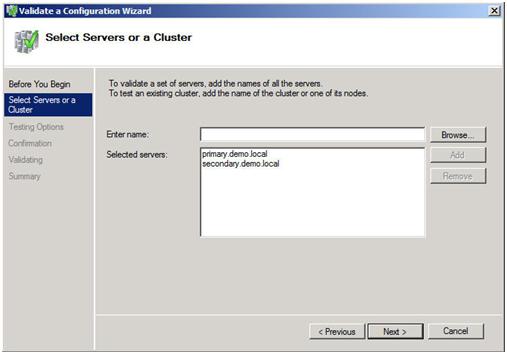
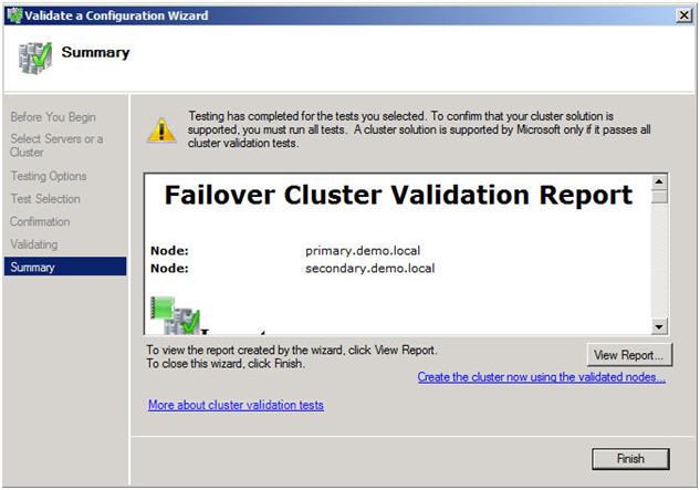
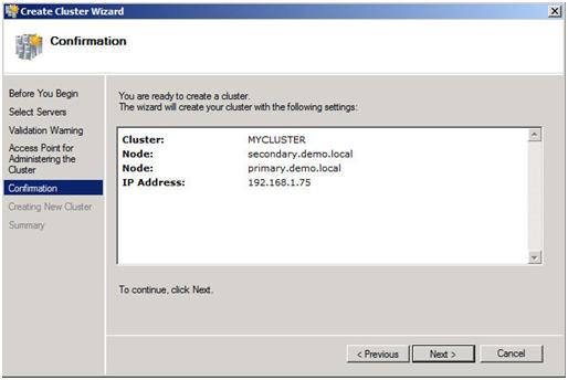
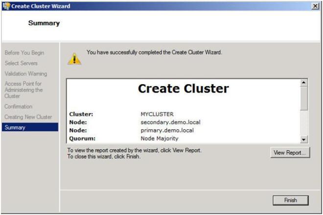
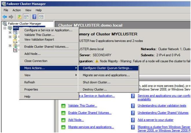
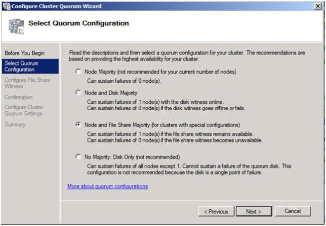
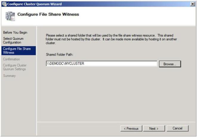
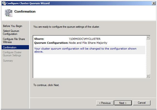
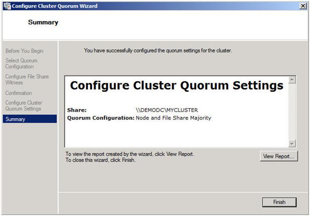
In Part 1 of this series, we took a look at the first steps required for building a multi-site cluster. We got to the point where we had a two node cluster that used a node and file share majority quorum, with no resources yet defined.

Let’s Continue

In this section we will start where we left off and look at how your replication solution will integrate with your failover clustering. Because each vendor’s replication solution will be implemented differently, it is hard to have one document that describes them all. The important thing to remember is that you want to purchase a replication solution that integrates with failover clustering and is certified by Microsoft. Your choices are basically array based, appliance based or host based replication solutions. EMC makes both appliance-based and array-based replication solutions and seem to do a great job at both. EMC’s John Toner maintains a blog that is dedicated to Geographically Dispersed Clusters and if you are going the EMC route, I’m sure he could lead you in the right direction. All the major vendors have solutions, you will just need to contact them to get the details.

SIOS DataKeeper

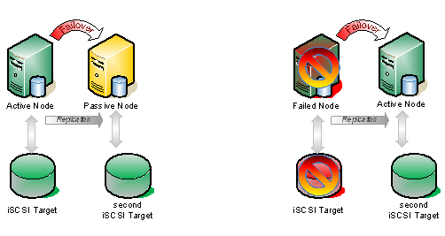
For this demonstration, I’m going to use a host based replication solution, SteelEye DataKeeper Cluster Edition, from my company, SteelEye Technology. It is so easy, that I thought instead of doing a long article, I would just record the steps and share it with you in a video. One of the advantages of host based replication is that you can utilize your existing storage, whether it is just some local attached disks, iSCSI or an expensive SAN. Host based replication can replicate across any storage devices.

Here is a summary of what you will see in the video.

  • Launch the SteelEye DataKeeper MMC Snap-in
    • Create a new DataKeeper job, define mirror end points, network, compression, etc.
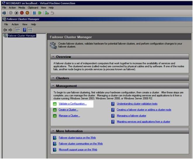
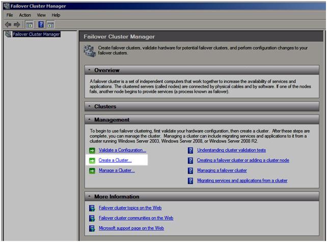
  • Launch the Failover Cluster MMC Snap-in
    • Create a Hyper-V resource
    • Add a DataKeeper Volume Resource
    • Edit the properties of the DataKeeper Volume resource to associate it with the mirror created earlier
    • Make the Virtual Machine configuration dependent upon the new DataKeeper volume resource

That’s it! You are now done. Sit back and enjoy your new Hyper-V multi-site cluster.

CLICK TO WATCH VIDEO

In Part 3 of this series, we will tackle SQL 2008 multi-site clusters on Windows Server 2008 R2. There are a few more steps and some tips and tricks you will definitely need to know, so make sure you check back to get all of the details. In the meantime, if you need assistance, leave me a comment or contact me through SIOS and I’d be glad to help you out.

Reproduced with permission from https://clusteringformeremortals.com/2009/09/18/step-by-step-configuring-a-2-node-multi-site-cluster-on-windows-server-2008-r2-%E2%80%93-part-2/

Filed Under: Clustering Simplified Tagged With: cluster, DataKeeper, DataKeeper Cluster Edition, failover clustering, integrate storage replication with failover clustering, Microsoft, storage replication

Step-By-Step: Configuring A 2-Node Multi-Site Cluster On Windows Server 2008 R2 – Part 1

January 22, 2018 by Jason Aw Leave a Comment

CREATING YOUR CLUSTER AND CONFIGURING THE QUORUM: NODE AND FILE SHARE MAJORITY

 INTRODUCTION

Welcome to Part 1 of my series “Step-by-Step: Configuring a 2-node multi-site cluster on Windows Server 2008 R2”. Before we jump right in to the details, let’s take a moment to discuss what exactly a multi-site cluster is and why I would want to implement one. Microsoft has a great webpage and white paper that you will want to download to get you all of the details, so I won’t repeat everything here. But basically a multi-site cluster is a disaster recovery solution and a high availability solution all rolled into one. A multi-site cluster gives you the highest recovery point objective (RTO) and recovery time objective (RTO) available for your critical applications. With the introduction of Windows Server 2008 failover clustering a multi-site cluster has become much more feasible with the introduction of cross subnet failover and support for high latency network communications.

I mentioned “cross-subnet failover” as a great new feature of Windows Server 2008 Failover Clustering, and it is a great new feature. However, SQL Server has not yet embraced this functionality, which means you will still be required to span your subnet across sites in a SQL Server multi-site cluster. As of Tech-Ed 2009, the SQL Server team reported that they plan on supporting this feature, but they say it will come sometime after SQL Server 2008 R2 is released. For the foreseeable future you will be stuck with spanning your subnet across sites in a SQL Server multi-site cluster. There are a few other network related issues that you need to consider as well, such as redundant communication paths, bandwidth and file share witness placement.

NETWORK CONSIDERATIONS

All Microsoft failover clusters must have redundant network communication paths. This ensures that a failure of any one communication path will not result in a false failover and ensures that your cluster remains highly available. A multi-site cluster has this requirement as well, so you will want to plan your network with that in mind. There are generally two things that will have to travel between nodes: replication traffic and cluster heartbeats. In addition to that, you will also need to consider client connectivity and cluster management activity. You will want to be sure that whatever networks you have in place, you are not overwhelming the network or you will have unreliable behavior. Your replication traffic will most likely require the greatest amount of bandwidth; you will need to work with your replication vendor to determine how much bandwidth is required.

With your redundant communication paths in place, the last thing you need to consider is your quorum model. For a 2-node multi-site cluster configuration, the Microsoft recommended configuration is a Node and File Share Majority quorum. For a detailed description of the quorum types, have a look at this article.

The most common cause of confusion with the Node and File Share Majority quorum is the placement of the File Share Witness. Where should I put the server that is hosting the file share? Let’s look at the options.

OPTION 1 – PLACE THE FILE SHARE IN THE PRIMARY SITE.

This is certainly a valid option for disaster recovery, but not so much for high availability. If the entire site fails (including the Primary node and the file share witness) the Secondary node in the secondary site will not come into service automatically, you will need to force the quorum online manually. This is because it will be the only remaining vote in the cluster. One out of three does not make a majority! Now if you can live with a manual step being involved for recovery in the event of a disaster, then this configuration may be OK for you.

OPTION 2 – PLACE THE FILE SHARE IN THE SECONDARY SITE.

This is not such a good idea. Although it solves the problem of automatic recovery in the event of a complete site loss, it exposes you to the risk of a false failover. Consider this…what happens if your secondary site goes down? In this case, your primary server (Node1) will go also go offline as it is now only a single node in the primary site and will no longer have a node majority. I can see no good reason to implement this configuration as there is too much risk involved.

OPTION 3 – PLACE THE FILE SHARE WITNESS IN A 3RD GEOGRAPHIC LOCATION

This is the preferred configuration as it allows for automatic failover in the event of a complete site loss and eliminates any the possibility of a failure of the secondary site causing the primary node to go offline. By having a 3rd site host the file share witness you have eliminated any one site as a single point of failure, so now the cluster will act as you expect and automatic failover in the event of a site loss is possible. Identifying a 3rd geographic location can be challenging for some companies, but with the advent of cloud based utility computing like Amazon EC2 and GoGrid, it is well within the reach of all companies to put a file share witness in the clouds and have the resiliency required for effective multi-site clusters. In fact, you may consider the cloud itself as your secondary data center and just failover to the cloud in the event of a disaster. I think the possibilities of cloud based computing and disaster recovery configurations are extremely enticing and in fact I plan on doing a whole blog post on a just that in the near future.

CONFIGURE THE CLUSTER

Now that we have the basics in place, let’s get started with the actual configuration of the cluster. You will want to add the Failover Clustering feature to both nodes of your cluster. For simplicity sake, I’ve called my nodes PRIMARY and SECONDARY. This is accomplished very easily through the Add Features Wizard as shown below.

Figure 1 – Add the Failover Clustering Role

Next you will want to have a look at your network connections. It is best if you rename the connections on each of your servers to reflect the network that they represent. This will make things easier to remember later.

Figure 2- Change the names of your network connections

You will also want to go into the Advanced Settings of your Network Connections (hit Alt to see Advanced Settings menu) of each server and make sure the Public network is first in the list.

Figure 3- Make sure your public network is first

Your private network should only contain an IP address and Subnet mask. No Default Gateway or DNS servers should be defined. Your nodes need to be able to communicate across this network, so make sure the servers can communicate across this network; add static routes if necessary.

Figure 4 – Private network settings

Once you have your network configured, you are ready to build your cluster. The first step is to “Validate a Configuration”. Open up the Failover Cluster Manager and click on Validate a Configuration.

Figure 5 – Validate a Configuration

The Validation Wizard launches and presents you the first screen as shown below. Add the two servers in your cluster and click Next to continue.

Figure 6 – Add the cluster nodes

A multi-site cluster does not need to pass the storage validation (see Microsoft article). Toskip the storage validation process,click on “Run only the tests I select” and click Continue.

Figure 7 – Select “Run only tests I select”

In the test selection screen, unselect Storage and click Next

Figure 8 – Unselect the Storage test

You will be presented with the following confirmation screen. Click Next to continue.

Figure 9 – Confirm your selection

If you have done everything right, you should see a summary page that looks like the following. Notice that the yellow exclamation point indicates that not all of the tests were run. This is to be expected in a multi-site cluster because the storage tests are skipped. As long as everything else checks out OK, you can proceed. If the report indicates any other errors, fix the problem, re-run the tests, and continue.

Figure 10 – View the validation report

You are now ready to create your cluster. In the Failover Cluster Manager, click on Create a Cluster.

Figure 11 – Create your cluster

The next step asks whether or not you want to validate your cluster. Since you have already done this you can skip this step. Note this will pose a little bit of a problem later on if installing SQL as it will require that the cluster has passed validation before proceeding. When we get to that point I will show you how to by-pass this check via a command line option in the SQL Server setup. For now, choose No and Next.

Figure 12 – Skip the validation test

The next step is that you must create a name for this cluster and IP for administering this cluster. This will be the name that you will use to administer the cluster, not the name of the SQL cluster resource which you will create later. Enter a unique name and IP address and click Next.

Note: This is also the computer name that will need permission to the File Share Witness as described later in this document.

Figure 13 – Choose a unique name and IP address

Confirm your choices and click Next.

Figure 14 – Confirm your choices

Congratulation, if you have done everything right you will see the following Summary page. Notice the yellow exclamation point; obviously something is not perfect. Click on View Report to find out what the problem may be.

Figure 15 – View the report to find out what the warning is all about

If you view the report, you should see a few lines that look like this.

Figure 16 – Error report

Don’t fret; this is to be expected in a multi-site cluster. Remember we said earlier that we will be implementing a Node and File Share Majority quorum. We will change the quorum type from the current Node Majority Cluster (not a good idea in a two node cluster) to a Node and File Share Majority quorum.

IMPLEMENTING A NODE AND FILE SHARE MAJORITY QUORUM

First, we need to identify the server that will hold our File Share witness. Remember, as we discussed earlier, this File Share witness should be located in a 3rd location, accessible by both nodes of the cluster. Once you have identified the server, share a folder as you normally would share a folder. In my case, I create a share called MYCLUSTER on a server named DEMODC.

The key thing to remember about this share is that you must give the cluster computer name read/write permissions to the share at both the Share level and NTFS level permissions. If you recall back at Figure 13, I created my cluster and gave it the name “MYCLUSTER”. You will need to make sure you give the cluster computer account read/write permissions as shown in the following screen shots.

Figure 17 – Make sure you search for Computers
Figure 18 – Give the cluster computer account NTFS permissions
Figure 19 – Give the cluster computer account share level permissions

Now with the shared folder in place and the appropriate permissions assigned, you are ready to change your quorum type. From Failover Cluster Manager, right-click on your cluster, choose More Actions and Configure Cluster Quorum Settings.

Figure 20 – Change your quorum type

On the next screen choose Node and File Share Majority and click Next.

Figure 21 – Choose Node and File Share Majority

In this screen, enter the path to the file share you previously created and click Next.

Figure 22 – Choose your file share witness

Confirm that the information is correct and click Next.

Figure 23 – Click Next to confirm your quorum change to Node and File Share Majority

Assuming you did everything right, you should see the following Summary page.

Figure 24 – A successful quorum change

Now when you view your cluster, the Quorum Configuration should say “Node and File Share Majority” as shown below.

Figure 25 – You now have a Node and File Share Majority quorum

The steps I have outlined up until this point apply to any multi-site cluster, whether it is a SQL, Exchange, File Server or other type of failover cluster. The next step in creating a multi-site cluster involves integrating your storage and replication solution into the failover cluster. This step will vary from depending upon your replication solution, so you really need to be in close contact with your replication vendor to get it right. In Part 2 of my series, I will illustrate how SteelEye DataKeeper Cluster Edition integrates with Windows Server Failover Clustering to give you an idea of how one of the replication vendor’s solutions works.

Other parts of this series will describe in detail how to install SQL, File Servers and Hyper-V in multi-site clusters. I will also have a post on considerations for multi-node clusters of three or more nodes.

Reproduced with permission from https://clusteringformeremortals.com/2009/09/15/step-by-step-configuring-a-2-node-multi-site-cluster-on-windows-server-2008-r2-%E2%80%93-part-1/

Filed Under: Clustering Simplified Tagged With: cluster, DataKeeper Cluster Edition, Microsoft

Remove The Weakest Link, Ensure High Availability Cluster Configuration

January 21, 2018 by Jason Aw Leave a Comment

Build A High Availability Cluster Configuration

When we build a High Availability Cluster Configuration, your application availability is only as good as its weakest link. What this means is that if you bought great servers with redundant everything (CPU, fans, power, RAID, RAM, etc) and a super deluxe SAN with multi-path connectivity. Coupled with multiple SAN switches and clustered your application with your favorite clustering software. You probably have a very reliable application – right? Well, not necessarily. Are the servers plugged into the same UPS? Are they on the same network switch? Are they cooled by the same AC unit? Are they in the same building? Is your SAN truly reliable? Any one of these issues among others is a single point of failure in a High Availability Cluster Configuration.

Seek And Remove The Weakest Link in Cluster Configuration

Of course, you have to know when “good enough” is “good enough”. Your budget and your SLAs will help decide what exactly is good enough. However, one area where I am concerned that people may be skimping is in the area of storage. With the advent of cheap or free iSCSI target software solutions, I am seeing some people recommend that you just throw some iSCSI target software on a spare server and voilà – instant shared storage.

Mind you I’m not talking about OEM iSCSI solutions that have built in failover technology and/or other availability features; or even storage virtualization solutions such as FalconStor. I’m talking about the guy who has a server running Windows Server 2008 that he has loaded up with storage and wants to turn it into an iSCSI target. This is great in a lab. But if you are serious about HA, you should think again. Even Microsoft only provides their iSCSI target software to qualified OEM builders experienced in delivering enterprise class storage arrays.

What You Are Actually Getting?

First of all, this is Windows. Not some hardened OS built to only serve storage. It will require maintenance, security updates, hardware fixes, etc. It basically has the same reliability as the application server you are trying to protect. Does it make sense to cluster your application servers. Yet use the same class of server and OS to host your storage? You basically have moved your single point of failure away from your application server and moved it to your storage server. It’s not a smart move as far as I am concerned.

Some of the Enterprise Class iSCSI target software includes synchronous and/or asynchronous replication software and snapshot capabilities. This functionality certainly helps in terms of your recovery point objective (RPO). Although it won’t help your recovery time objective (RTO) unless the failover is automatic and seamless to your clustering software. Let’s say the primary iSCSI storage array fails in the middle of the night. Who is going to be there to activate the replicated copy? You may be down for quite some time before you even realize there is a problem. Again, this may be “good enough”; you just need to be aware of what you are signing up for. Is that the High Availability Cluster Configuration you’re seeking?

SIOS DataKeeper

One thing you can do to improve the reliability of your iSCSI target server is to use a replication product such as SteelEye DataKeeper Cluster Edition to eliminate the single point of failure. Let me illustrate.

Typical Shared Storage Configuration
Figure 1 – Typical Shared Storage Configuration. In the event that the iSCSI target becomes unavailable, all the nodes go offline.

If we take the same configuration shown above and add a hot standby iSCSI target using SteelEye DataKeeper Cluster Edition to do replication AND automatic failover, you have just given you iSCSI target solution a whole new level of availability. That solution would look very much like this.

DataKeeper Cluster Edition - High Availability Cluster Configuration
Figure 2 – In this scenario, DataKeeper Cluster Edition is replicating the iSCSI attached volume on the active node to the iSCSI attached volume on the passive node, which is connected to an entirely different iSCSI target server.

The key difference in the solution which utilizes SteelEye DataKeeper Cluster Edition vs. replication solutions provide by some iSCSI target vendors is in the integration with WSFC. The question to ask of your iSCSI solution vendor is this…

What happens if I pull the power cord on the active iSCSI target server?

If the recovery process is a manual procedure, it is not a true HA solution. But what if it is automatic and completely integrated with WSFC? Then you have a much higher level of availability and have eliminated the iSCSI array as a single point of failure.

Chat with us to also achieve High Availability Cluster Configuration

Reproduced with permission from Clusteringformortals.

Filed Under: Clustering Simplified, Datakeeper Tagged With: cluster, DataKeeper Cluster Edition, High Availability, high availability cluster configuration, SANLess Clustering

How Can Asynchronous Replication Be Used In A Multi-Site Cluster? Isn’t The Data Out Of Sync?

January 18, 2018 by Jason Aw Leave a Comment

How Can Asynchronous Replication Be Used In A Multi-Site Cluster? Isn’t The Data Out Of Sync?

I have been asked this question more than a few times, so I thought I would answer it in my first blog post.  The basic answer is yes, you can lose data in an unexpected failure when using asynchronous replication in a multi-site cluster.  In an ideal world, every company would have a dark fiber connection to their DR site and use synchronous replication with their multi-site cluster, eliminating the possibility of data loss.  However, the reality is that in many cases, the WAN connectivity to the DR site has too much latency to support synchronous replication.  In such cases, asynchronous replication is an excellent alternative.

What Are My Options?

There are more than a few options when choosing an asynchronous replication solution to use with your WSFC multi-site cluster. This includes array based solutions from companies like EMC, IBM, HP, etc. and host based solutions, like the one that is near and dear to me, “SteelEye DataKeeper Cluster Edition“.  Since I know DataKeeper best, I will explain how this all works from DataKeeper’s prospective.

What About SteelEye DataKeeper?

When using SteelEye DataKeeper and asynchronous replication, we allow a certain number of writes to be stored in the async queue.  The number of writes which can be queued is determined by the “high water mark”. This is an adjustable value used by DataKeeper to determine how much data can be in the queue before the mirror state is changed from “mirroring” to “paused”.  A “paused” state is also entered anytime there is a communication failure between the secondary and primary server. While in a paused state, automatic failover in a multi-site cluster is disabled, limiting the amount of data that can be lost in an unexpected failure.  If the original data set is deemed “lost forever”, then the remaining data on the target server can be manually unlocked and the cluster node can then be brought into service.

While in the “paused” state, DataKeeper allows the async queue to drain until we reach the “low water mark”, at which point the mirror enters a “resync” state until all of the data is once again is in sync.  At that point, the mirror is once again in the “mirroring” state and automatic failover is once again enabled.

As long as your WAN link is not saturated or broken, you should never see more than a few writes at any given time in this async queue.   In an unexpected failure (think pulled power cord) you will lose any write that is in the async queue.  This is the trade off you make when you want the awesome recovery point objective (RPO) and recovery time objective (RTO) which you achieve with a multi-site cluster, but your WAN link has too much latency to effectively support synchronous replication.

Try The SteelEye DataKeeper

Take time to monitor the DataKeeper Async Queue via the Windows Performance Logs and Alerts. I think you will be pleasantly surprised to find that most of the time the async queue is empty due to the efficiency of the DataKeeper replication engine.  Even in times of heavy writes, the async queue seldom grows very large and always drains almost immediately. So the amount of data that is at risk at any given time is minimal.  Compared to the alternative in a disaster to restore from last night’s backup, the number of writes you could lose in an unexpected failure using asynchronous replication is minimal!

Of course, there are some instances where even losing a single write is not tolerable.  In those cases, it is recommended to use SteelEye DataKeeper’s synchronous replication option across a high-speed, low latency LAN or WAN connection.

Reproduced with permission from Clusteringformeremortals.com

Filed Under: Clustering Simplified, Datakeeper Tagged With: cluster

SIOS Awarded 2014 InfoTech Spotlight Data Center Excellence Award

December 23, 2014 by sios2017

SIOS DataKeeper Cluster Edition Recognized for Excellence

SAN MATEO, CA – December 22, 2014 – SIOS Technology Corp. (www.us.sios.com), maker of SAN and #SANLess clustering software products, today announced that TMC, a global, integrated media company, named SIOS DataKeeper Cluster Edition as a 2014 Data Center Excellence Award winner, presented by infoTECH Spotlight.

SIOS DataKeeper Cluster Edition software enables SANLess clustering for high availability and disaster protection in Windows Server Failover Clustering environments. It protects data in physical, virtual, and cloud environments and provides enterprise-class protection for all server workloads at a fraction of the cost of SAN-based replication. SIOS DataKeeper synchronizes local storage in different cluster nodes using fast, efficient, block-level replication to transfers data with minimal bandwidth and delivers incredibly fast replication speeds without the need for additional hardware accelerators or compression devices. It enables high availability cluster protection without the cost or single point of failure risk of SAN-based clusters.

“SOIS DataKeeper Cluster Edition lets customers build a cluster using their choice of industry-standard hardware and local attached storage in a SANLess configuration, making them easy to use and easy to own,” said Jerry Melnick, COO, SIOS Technology. “SIOS lets you run your business critical applications in a physical, virtual or cloud environment without sacrificing performance, high availability or disaster protection.”

“SIOS has displayed its commitment to quality and innovation in the development of the data center industry,” said Rich Tehrani, CEO, TMC. “I look forward to witnessing continued excellence from SIOS and their efforts toward improving the future of the data center industry.”

The 2014 Data Center Excellence Award recognizes the most innovative and enterprising data center vendors who offer infrastructure or software, servers or cooling systems, cabling or management applications.

About InfoTech Spotlight
InfoTech Spotlight brings extensive daily content focused on information technology. Visitors will find free industry news, communities, channels, blogs, feature articles, videos, whitepapers and other resources. The site keeps readers informed about developments across topics including software, hardware, security and networking. InfoTech Spotlight is powered by TMCnet, the leading communications and technology site in the World attracting two million unique visitors monthly according to Webtrends. Please visit: infoTECH Spotlight for more information.

About TMC
TMC is a global, integrated media company that supports clients’ goals by building communities in print, online, and face to face. TMC publishes multiple magazines including Cloud Computing, M2M Evolution, Customer, and Internet Telephony. TMCnet is the leading source of news and articles for the communications and technology industries, and is read by as many as 1.5 million unique visitors monthly. TMC produces a variety of trade events, including ITEXPO, the world’s leading business technology event, as well as industry events: Asterisk World; AstriCon; ChannelVision (CVx) Expo; Cloud4SMB Expo; Customer Experience (CX) Hot Trends Symposium; DevCon5 – HTML5 & Mobile App Developer Conference; LatinComm Conference and Expo; M2M Evolution Conference & Expo; Mobile Payment Conference; Software Telco Congress, StartupCamp; Super Wi-Fi & Shared Spectrum Summit; SIP Trunking-Unified Communications Seminars; Wearable Tech Conference & Expo; WebRTC Conference & Expo III; and more. Visit TMC Events for additional information.

About SIOS Technology Corp.
SIOS Technology Corp. makes SAN and #SANLess software solutions that make clusters easy to use and easy to own. An essential part of any cluster solution, SIOS SAN and #SANLess software provides the flexibility to build Clusters Your Way™ to protect your choice of Windows or Linux environment in any configuration (or combination) of physical, virtual and cloud (public, private, and hybrid) without sacrificing performance or availability. The unique SIOS #SANLess clustering solution allows you to configure clusters with local storage, eliminating both the cost and the single-point-of-failure risk of traditional shared (SAN) storage. Founded in 1999, SIOS Technology Corp. (www.us.sios.com) is headquartered in San Mateo, California, and has offices throughout the United States, United Kingdom and Japan.

# # #

SIOS, SIOS Technology, SIOS DataKeeper, SIOS Protection Suite, Clusters Your Way, and associated logos are registered trademarks or trademarks of SIOS Technology Corp. and/or its affiliates in the United States and/or other countries. All other trademarks are the property of their respective owners.

Contacts:

For SIOS Technology
Beth Winkowski
Winkowski Public Relations, LLC
Phone: 978-649-7189
Email: bethwinkowski@US.SIOS.com

TMC Contact
Rebecca Conyngham
Marketing Manager
Phone: 203-852-6800, ext. 287
Email: rconyngham@tmcnet.com


Filed Under: News and Events, Press Releases Tagged With: cluster, DataKeeper Cluster Edition

  • « Previous Page
  • 1
  • …
  • 6
  • 7
  • 8
  • 9
  • Next Page »

Recent Posts

  • Announcing LifeKeeper/SSP/DKCE for Windows 8.11.0: Enhanced Stability, Security, and Support
  • Why an Effective Patch Management Strategy Is Essential for IT Resilience
  • Streamlining External Communication for Emergency Procedures
  • Avoiding the Disaster You Don’t See Coming: Building a Resilient DR Plan
  • The Best Rolling Upgrade Strategy to Enhance Business Continuity

Most Popular Posts

Maximise replication performance for Linux Clustering with Fusion-io
Failover Clustering with VMware High Availability
create A 2-Node MySQL Cluster Without Shared Storage
SAP for High Availability Solutions For Linux
Bandwidth To Support Real-Time Replication
The Availability Equation – High Availability Solutions.jpg
Choosing Platforms To Replicate Data - Host-Based Or Storage-Based?
Guide To Connect To An iSCSI Target Using Open-iSCSI Initiator Software
Best Practices to Eliminate SPoF In Cluster Architecture
Step-By-Step How To Configure A Linux Failover Cluster In Microsoft Azure IaaS Without Shared Storage azure sanless
Take Action Before SQL Server 20082008 R2 Support Expires
How To Cluster MaxDB On Windows In The Cloud

Join Our Mailing List

Copyright © 2025 · Enterprise Pro Theme on Genesis Framework · WordPress · Log in