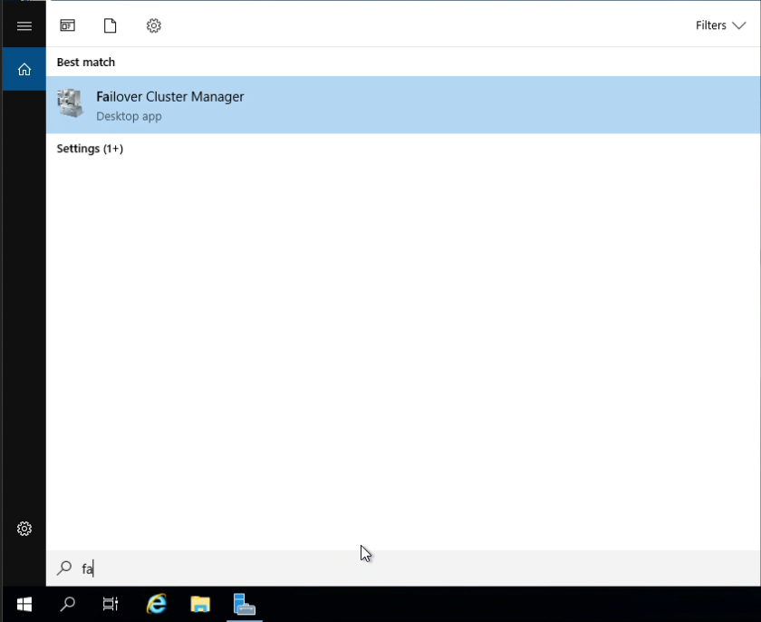
How to get the most out of your “GET” commands in DataKeeper
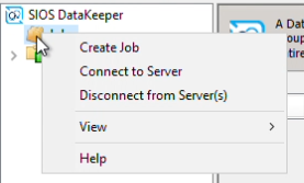
In part 2 of the three-part DataKeeper dashboard blog series, this blog is a follow up from DataKeeper UI vs. Car Dashboards blog. As with your car, when those indicators (traffic light colors) on your dashboard flash, you pop the hood to identify what they represent. Starting points:
- Battery Light = check battery, cable connections, alternator, etc.
- Oil Light = checking the dipstick for low, high or no oil (No oil, DON’T MOVE YOUR CAR)
- Coolant Light = Is there any coolant/water in the overfill tank?
“Popping the hood” on your DataKeeper Cluster Edition software has several similarities and it often means using command line interface for DataKeeper Administration. As for Using EMCMD (Extended Mirroring Command) with SIOS DataKeeper, the GET commands make up 1/3 of the most commonly used tasks/commands of the approximately 48 commands. Note that they are informational only and will not impact your nodes. Below are a few helpful Get commands and their usage to identify the reasons for warning colors in your DataKeeper User Interface/DataKeeper.msc (traffic light colors) in the areas of Storage, Networking and Other.
Note:
From an elevated/Administrator command prompt as always use:
cd %extmirrbase% (This is just a shortcut to the install path <root>\Program Files (x86)\SIOS\DataKeeper>)
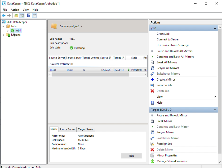
Obtaining Status of your DataKeeper Mirrors
A great place to start your initial triage below:
- getmirrorvolinfo (Other) It is the most heavily used tool as it provides the Mirror roles, Source/Target and the 5 different states a Mirror can be in. It can be run on the source or the target to check to see if the mirror configuration exists.
- getserviceinfo (Other) – Great information about
- the Driver Version and DataKeeper Service Version
- and the time the SIOS DataKeeper Service was started/restarted
- getcompletevolumelist (Storage/Network) – a total list
- of all disks
- DataKeeper and non-DataKeeper Volumes
- their Role (Source/Target) and Total Capacity (in bytes)
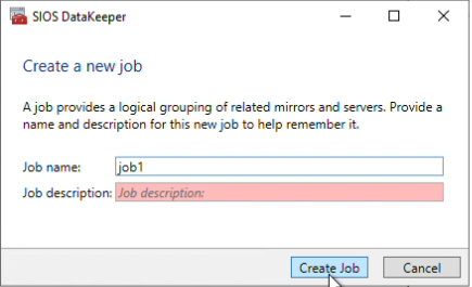
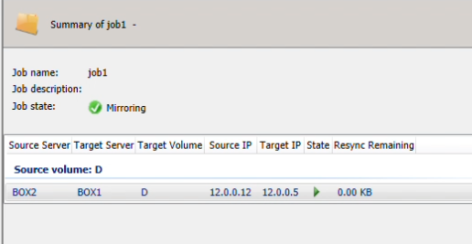
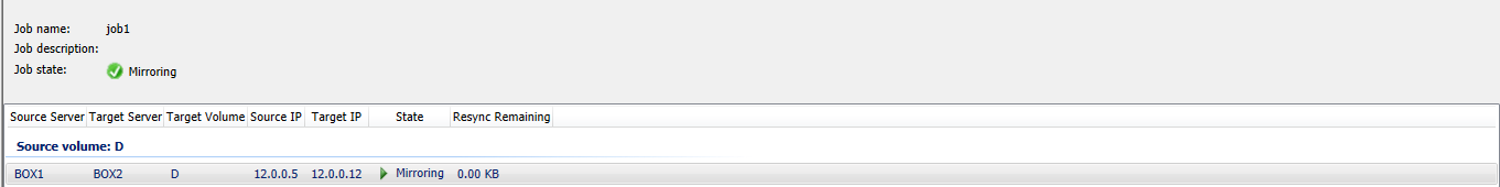
- getjobinfo (Storage/Network) this shows/echos the job information listed in the DataKeeper console
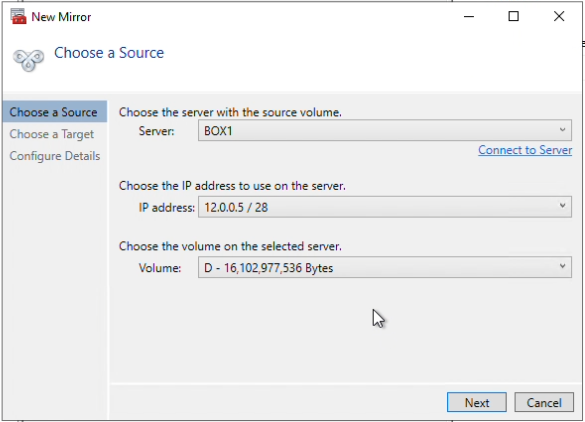
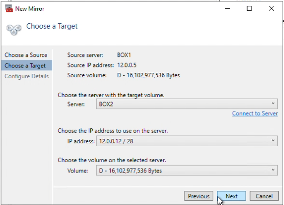
- getvolumeinfo (Storage,Network) Great utility when
- comparing the Total Drive Capacity of the Source (diskmgmt.msc) and Target Volumes (bytes)
- IP addresses and present Mirror status
Cross-referencing DataKeeper “GET” commands to various Windows Server Commands
- Getjobinfo and “ipconfig /all” (Networking)
- Are the IP addresses identical in both outputs? If the Mirror Replication is to be segmented to another network then the getjobinfo must match the ipconfig /all output. Executing a changemirrorendpoints will correct this discrepancy (to be discussed in another blog)
- Also the mirrorendpoints information from the getjobinfo output should match the IP addresses locate in the ipconfig /all output
- Are the IP addresses identical in both outputs? If the Mirror Replication is to be segmented to another network then the getjobinfo must match the ipconfig /all output. Executing a changemirrorendpoints will correct this discrepancy (to be discussed in another blog)
- After performing a Resize of the existing Source and Target Volumes, does the emcmd . getvolumeinfo command reflect a different Total Space than the DISKPART command and its Size? Via DISKPART a “extend” or “extend filesystem” may be required so as the resized volumes are recognized by the Operating System
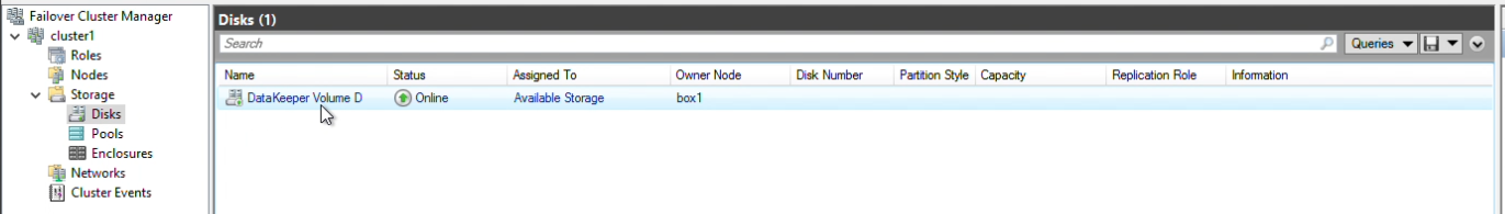
- Getcompletevolumelist has information similar to that of the Disk Management applet (diskmgmt.msc)
- File System type
- Volume Total Space (bytes)
- Getvolumeinfo provides similar output
- Getserviceinfo as well as “net start” can provide status about the SIOS DataKeeper Service; if it is Start/Stop
Take Charge of DataKeeper: Apply Your GET Command Knowledge Now
Now that you are armed with some basic knowledge about the lights on your car’s dashboard you will become a DIYer when it comes to DataKeeper Administration in blog 3 in the DataKeeper Dashboard series.
Reproduced with permission from SIOS