Step-By-Step Guide To Set Up Low Cost SAN With Linux Software iSCSI Target
A software iSCSI target can be a great way to set up shared storage when you don’t have enough dough to afford pricey SAN hardware. The iSCSI target acts just like a real hardware iSCSI array, except it’s just a piece of software running on a traditional server (or even a VM!). Setting up an iSCSI target is an easy and low cost way to get the shared storage you need. It does not matter if you’re using a clustering product like Microsoft Windows Server Failover Clustering (WSFC), a cluster filesystem such as GFS or OCFS. Or even if you’re wanting to get the most out of your virtualization platform (be it VMware, XenServer, or Hyper-V) by enabling storage pooling and live migration.
About Lio-Target
Recently, the Linux kernel has adopted LIO-Target as the standard iSCSI target for Linux. LIO-Target is available in Linux kernels 3.1 and higher. LIO-Target supports SCSI-3 Persistent Reservations, which are required by Windows Server Failover Clustering, VMware vSphere, and other clustering products. The LUNs (disks) presented by the iSCSI target can be entire disks, partitions, or even just plain old files on the filesystem. LIO-Target supports all of these options.
Below, we’ll walk through the steps to configure LIO-Target on an Ubuntu 12.04 server. Other recent distros will probably work also, but the steps may vary slightly.
Configuration Steps
First, install the Lio-target packages:
# apt-get install –no-install-recommends targetcli python-urwid
Lio-target is controlled using the targetcli command line utility.
The first step is to create the backing store for the LUN. In this example, we’ll use a file-backed LUN, which is just a normal file on the filesystem of the iSCSI target server.
# targetcli
/> cd backstores/
/backstores> ls
o- backstores …………………………………………………… […]
o- fileio …………………………………………. [0 Storage Object]
o- iblock …………………………………………. [0 Storage Object]
o- pscsi ………………………………………….. [0 Storage Object]
o- rd_dr ………………………………………….. [0 Storage Object]
o- rd_mcp …………………………………………. [0 Storage Object]
/backstores> cd fileio
/backstores/fileio> help create (for help)
/backstores/fileio> create lun0 /root/iscsi-lun0 2g (create 2GB file-backed LUN)
Second Step
Now the LUN is created. Half way there to Set up Low Cost SAN with Linux Software iSCSI Target. Next we’ll set up the target so client systems can access the storage.
/backstores/fileio/lun0> cd /iscsi
/iscsi> create (create iqn and target port group)
Created target iqn.2003-01.org.linux-iscsi.murray.x8664:sn.31fc1a672ba1.
Selected TPG Tag 1.
Successfully created TPG 1.
Entering new node /iscsi/iqn.2003-01.org.linux-iscsi.murray.x8664:sn.31fc1a672ba1/tpgt1
/iscsi/iqn.20…a672ba1/tpgt1> set attribute authentication=0 (turn off chap auth)
/iscsi/iqn.20…a672ba1/tpgt1> cd luns
/iscsi/iqn.20…a1/tpgt1/luns> create /backstores/fileio/lun0 (create the target LUN)
Selected LUN 0.
Successfully created LUN 0.
Entering new node /iscsi/iqn.2003-01.org.linux-iscsi.murray.x8664:sn.31fc1a672ba1/tpgt1/luns/lun0
/iscsi/iqn.20…gt1/luns/lun0> cd ../../portals
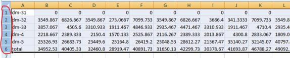
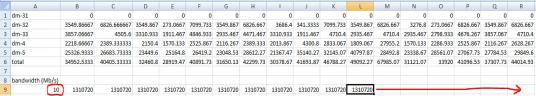
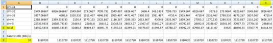
iSCSI traffic can consume a lot of bandwidth. You’ll probably want the iSCSI traffic to be on a dedicated (or SAN) network, rather than your public network.
/iscsi/iqn.20…tpgt1/portals> create 10.10.102.164 (create portal to listen for connections)
Using default IP port 3260
Successfully created network portal 10.10.102.164:3260.
Entering new node /iscsi/iqn.2003-01.org.linux-iscsi.murray.x8664:sn.31fc1a672ba1/tpgt1/portals/10.10.102.164:3260
/iscsi/iqn.20….102.164:3260> cd ..
/iscsi/iqn.20…tpgt1/portals> create 10.11.102.164
Using default IP port 3260
Successfully created network portal 10.11.102.164:3260.
Entering new node /iscsi/iqn.2003-01.org.linux-iscsi.murray.x8664:sn.31fc1a672ba1/tpgt1/portals/10.11.102.164:3260
/iscsi/iqn.20…102.164:3260> cd ../../acls
Final Step
Register the iSCSI initiators (client systems) to Set up Low Cost SAN with Linux Software iSCSI Target. To do this, you’ll need to find the initiator names of the systems. For Linux, this will usually be in /etc/iscsi/initiatorname.iscsi. For Windows, the initiator name is found in the iSCSI Initiator Properties Panel in the Configuration Tab.
/iscsi/iqn.20…a1/tpgt1/acls> create iqn.1994-05.com.redhat:f5b312caf756 (register initiator — this IQN is the IQN of the initiator — do this for each initiator that will access the target)
Successfully created Node ACL for iqn.1994-05.com.redhat:f5b312caf756
Created mapped LUN 0.
Entering new node /iscsi/iqn.2003-01.org.linux-iscsi.murray.x8664:sn.31fc1a672ba1/tpgt1/acls/iqn.1994-05.com.redhat:f5b312caf756
/iscsi/iqn.20….102.164:3260> cd /
Now, remember to save the configuration. Without this step, the configuration will not be persistent.
/> saveconfig (SAVE the configuration!)
/> exit
You’ll now need to connect your initiators to the target. Generally you’ll need to provide the IP address of the target to connect to it. After the connection is made, the client systems will see a new disk. The disk will need to be formatted before use.
And that’s it! You’re ready to use your new SAN. Have fun!
Having problems to Set up Low Cost SAN with Linux Software iSCSI Target, read our other helpful articles
Reproduced with permission from Linuxclustering