How to use Azure Site Recovery (ASR) to replicate a Windows Server Failover Cluster (WSFC) that uses SIOS DataKeeper for cluster storage
Intro
So you have built a SQL Server Failover Cluster Instance (FCI), or maybe an SAP ASCS/ERS cluster in Azure. Each node of the cluster resides in a different Availability Zone (AZ), or maybe you have strict latency requirements and are using Placement Proximity Groups (PPG) and your nodes all reside in the same Availability Set. Regardless of the scenario, you now have a much higher level of availability for your business critical application than if you were just running a single instance.
Now that you have high availability (HA) covered, what are you going to do for disaster recovery? Regional disasters that take out multiple AZs are rare, but as recent history has shown us, Mother Nature can really pack a punch. You want to be prepared should an entire region go offline.
Azure Site Recovery (ASR) is Microsoft’s disaster recovery-as-a-service (DRaaS) offering that allows you to replicate entire VMs from one region to another. It can also replicate virtual machines and physical servers from on-prem into Azure, but for the purpose of this blog post we will focus on the Azure Region-to-Region DR capabilities.
Setting up Azure Site Recovery
We are going to assume you have already built your cluster using SIOS DataKeeper. If not, here are some pointers to help get you started.
Failover Cluster Instances with SQL Server on Azure VMs
SIOS DataKeeper Cluster Edition for the SAP ASCS/SCS cluster share disk
We are also going to assume you are familiar with Azure Site Recovery. Instead of yet another guide on setting up ASR, I suggest you read the latest documentation from Microsoft. This article will focus instead on some things you may not have considered and the specific steps required to fix your cluster after a failover to a different subnet.
Paired Regions
Before you start down the DR path, you should be aware of the concept of Azure Paired Regions. Every Region in Azure has a preferred DR Region. If you want to learn more about Paired Regions, the documentation provides a great background. There are some really good benefits of using your paired region, but it’s really up to you to decide on what region you want to use to host your DR site.
Cloud Witness Location
When you originally built your cluster you had to choose a witness type for your quorum. You may have selected a File Share Witness or a Cloud Witness. Typically either of those witness types should reside in an AZ that is separate from your cluster nodes.
However, when you consider that, in the event of a disaster, your entire cluster will be running in your DR region, there is a better option. You should use a cloud witness, and place it in your DR region. By placing your cloud witness in your DR region, you provide resiliency not only for local AZ failures, but it also protects you should the entire region fail and you have to use ASR to recover your cluster in the DR region. Through the magic of Dynamic Quorum and Dynamic Witness, you can be sure that even if your DR region goes offline temporarily, it will not impact your production cluster.
Multi-VM Consistency
When using ASR to replicate a cluster, it is important to enable Multi-VM Consistency to ensure that each cluster node’s recovery point is from the same point in time. That ensures that the DataKeeper block level replication occurring between the VMs will be able to continue after recovery without requiring a complete resync.
Crash Consistent Recovery Points
Application consistent recovery points are not supported in replicated clusters. When configuring the ASR replication options do not enable application consistent recovery points.
Keep IP Address After Failover?
When using ASR to replicate to your DR site there is a way to keep the IP address of the VMs the same. Microsoft described it in the article entitled Retain IP addresses during failover. If you can keep the IP address the same after failover it will simplify the recovery process since you won’t have to fix any cluster IP addresses or DataKeeper mirror endpoints, which are based on IP addresses.
However, in my experience, I have never seen anyone actually follow the guidance above, so recovering a cluster in a different subnet will require a few additional steps after recovery before you can bring the cluster online.
Your First Failover Attempt
Recovery Plan
Because you are using Multi-VM Consistency, you have to failover your VMs using a Recovery Plan. The documentation provides pretty straightforward guidance on how to do that. A Recovery Plan groups the VMs you want to recover together to ensure they all failover together. You can even add multiple groups of VMs to the same Recovery Plan to ensure that your entire infrastructure fails over in an orderly fashion.
A Recovery Plan can also launch post recovery scripts to help the failover complete the recovery successfully. The steps I describe below can all be scripted out as part of your Recovery Plan, thereby fully automating the complete recovery process. We will not be covering that process in this blog post, but Microsoft documents this process.
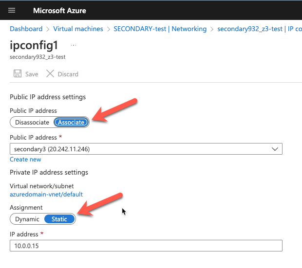
Static IP Addresses
As part of the recovery process you want to make sure the new VMs have static IP addresses. You will have to adjust the interface properties in the Azure Portal so that the VM always uses the same address. If you want to add a public IP address to the interface you should do so at this time as well.
Network Configuration
After the replicated VMs are successfully recovered in the DR site, the first thing you want to do is verify basic connectivity. Is the IP configuration correct? Are the instances using the right DNS server? Is name resolution functioning correctly? Can you ping the remote servers?
If there are any problems with network communications then the rest of the steps described below will be bound to fail. Don’t skip this step!
Load Balancer
As you probably know, clusters in Azure require you to configure a load balancer for client connectivity to work. The load balancer does not fail over as part of the Recovery Plan. You need to build a new load balancer based on the cluster that now resides in this new vNet. You can do this manually or script this as part of your Recovery Plan to happen automatically.
Network Security Groups
Running in this new subnet also means that you have to specify what Network Security Group you want to apply to these instances. You have to make sure the instances are able to communicate across the required ports. Again, you can do this manually, but it would be better to script this as part of your Recovery Plan.
Fix the IP Cluster Addresses
If you are unable to make the changes described earlier to recover your instances in the same subnet, you will have to complete the following steps to update your cluster IP addresses and the DataKeeper addresses for use in the new subnet.
Every cluster has a core cluster IP address. What you will see if you launch the WSFC UI after a failover is that the cluster won’t be able to connect. This is because the IP address used by the cluster is not valid in the new subnet.
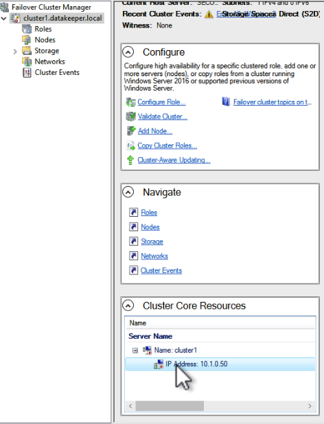
If you open the properties of that IP Address resource you can change the IP address to something that works in the new subnet. Make sure to update the Network and Subnet Mask as well.

Once you fix that IP Address you will have to do the same thing for any other cluster address that you use in your cluster resources.
Fix the DataKeeper Mirror Addresses
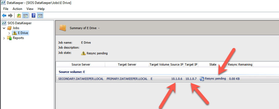
SIOS DataKeeper mirrors use IP addresses as mirror endpoints. These are stored in the mirror and mirror job. If you recover a DataKeeper based cluster in a different subnet, you will see that the mirror comes up in a Resync Pending state. You will also notice that the Source IP and the Target IP reflect the original subnet, not the subnet of the DR site.
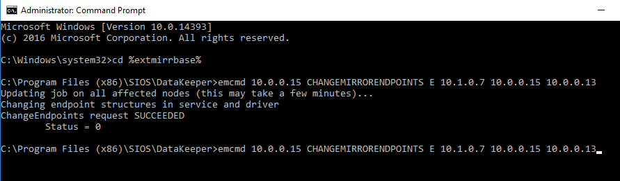
Fixing this issue involves running a command from SIOS called CHANGEMIRRORENDPOINTS. The usage for CHANGEMIRRORENDPOINTS is as follows.
emcmd <NEW source IP> CHANGEMIRRORENDPOINTS <volume letter> <ORIGINAL target IP> <NEW source IP> <NEW target IP>
In our example, the command and output looked like this.
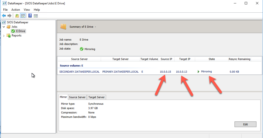
After the command runs, the DataKeeper GUI will be updated to reflect the new IP addresses as shown below. The mirror will also go to a mirroring state.
Conclusions
You have now successfully configured and tested disaster recovery of your business critical applications using a combination of SIOS DataKeeper for high availability and Azure Site Recovery for disaster recovery. If you have questions, or would like to consult with SIOS to help you design and implement high availability and disaster recovery for your business critical applications like SQL Server, SAP ASCS and ERS, SAP HANA, Oracle or other business critical applications, please reach out to us.
Reproduced with permission from SIOS