Step-By-Step: ISCSI Target Server Cluster In Azure
I recently helped someone build an iSCSI target server cluster in Azure and realized that I never wrote a step-by-step guide for that particular configuration. So to remedy that, here are the step-by-step instructions in case you need to do this yourself.
Pre-Requisites
I’m going to assume you are fairly familiar with Azure and Windows Server, so I’m going to spare you some of the details. Let’s assume you have at least done the following as a pre-requisite
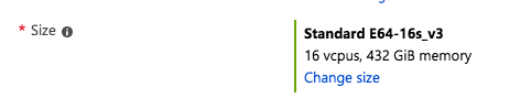
- Provision two servers (SQL1, SQL2) each in a different Availability Zone (Availability Set is also possible, but Availability Zones have a better SLA)
- Assign static IP addresses to them through the Azure portal
- Joined the servers to an existing domain
- Enabled the Failover Clustering feature and the iSCSI Target Server feature on both nodes
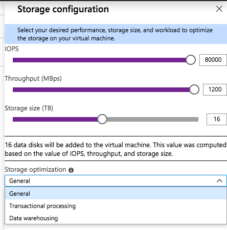
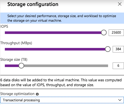
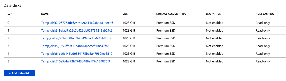
- Add three Azure Premium Disk to each node.
NOTE: this is optional, one disk is the minimum required. For increased IOPS we are going to stripe three Premium Azure Disks together in a storage pool and create a simple (RAID 0) virtual disk - SIOS DataKeeper is going to be used to provided the replicated storage used in the cluster. If you need DataKeeper you can request a trial here.
Create Local Storage Pool
Once again, this step is completely optional, but for increased IOPS we are going to stripe together three Azure Premium Disks into a single Storage Pool. You might be tempted to use Dynamic Disk and a spanned volume instead, but don’t do that! If you use dynamic disks you will find out that there is some general incompatibility that will prevent you from creating iSCSI targets later.
Don’t worry, creating a local Storage Pool is pretty straight forward if you are aware of the pitfalls you might encounter as described below. The official documentation can be found here.
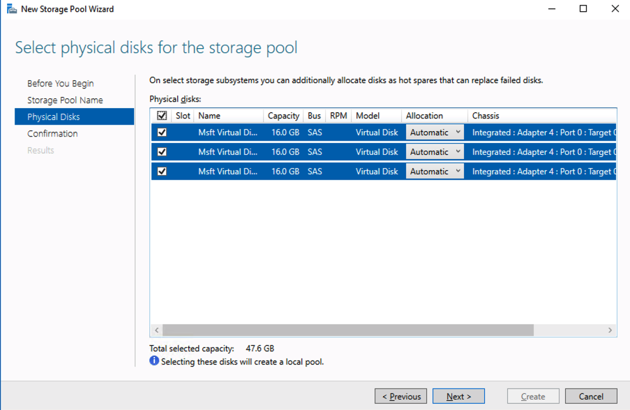
Pitfall #1 – although the documentation says the minimum size for a volume to be used in a storage pool is 4 GB, I found that the P1 Premium Disk (4GB) was NOT recognized. So in my lab I used 16GB P3 Premium Disks.
Pitfall #2 – you HAVE to have at least three disks to create a Storage Pool.
Pitfall #3 – create your Storage Pool before you create your cluster. If you try to do it after you create your cluster you are going to wind up with a big mess as Microsoft tries to create a clustered storage pool for you. We are NOT going to create a clustered storage pool, so avoid that mess by creating your Storage Pool before you create the cluster. If you have to add a Storage Pool after the cluster is created you will first have to evict the node from the cluster, then create the Storage Pool.
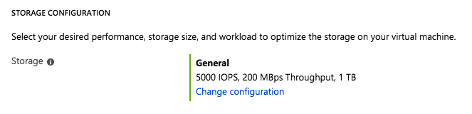
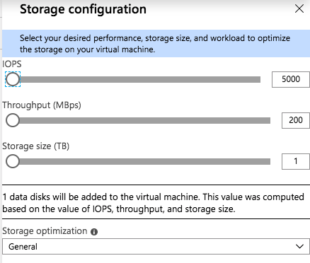
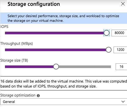
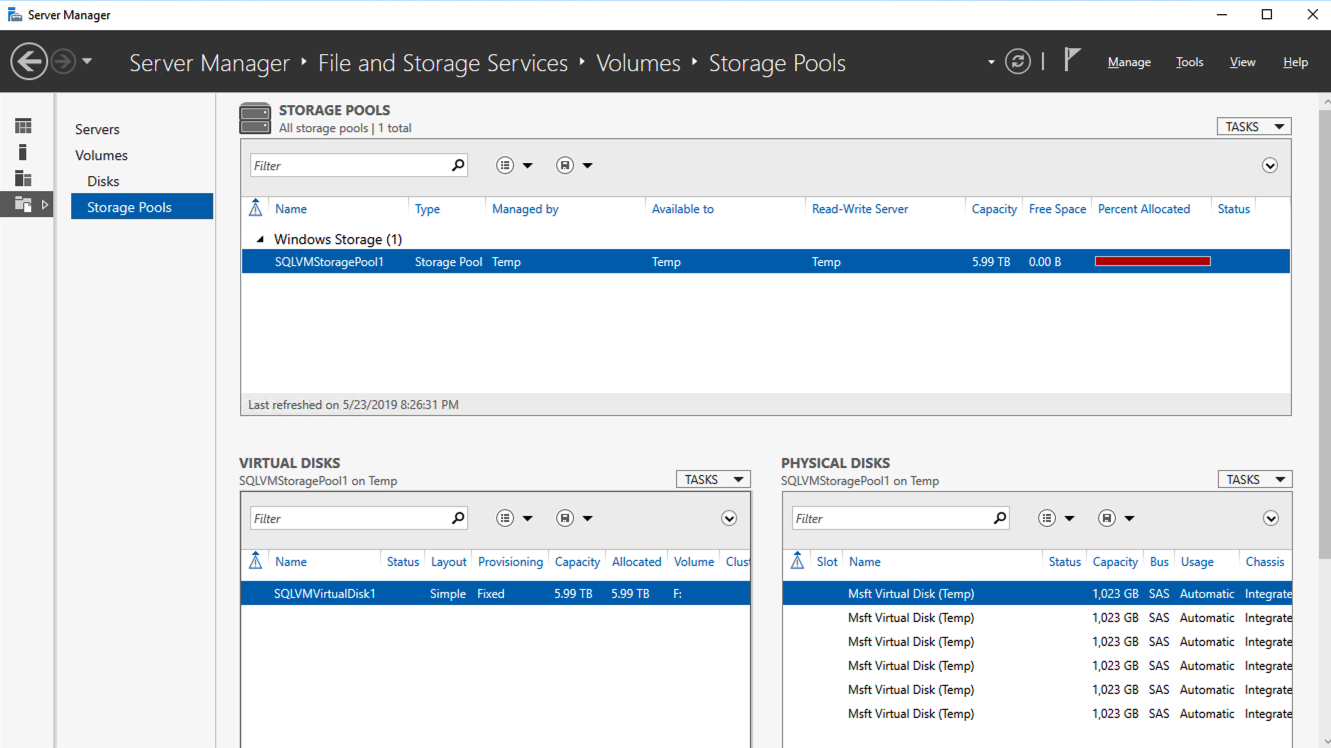
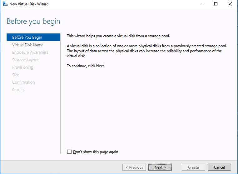
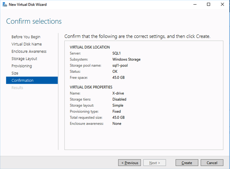
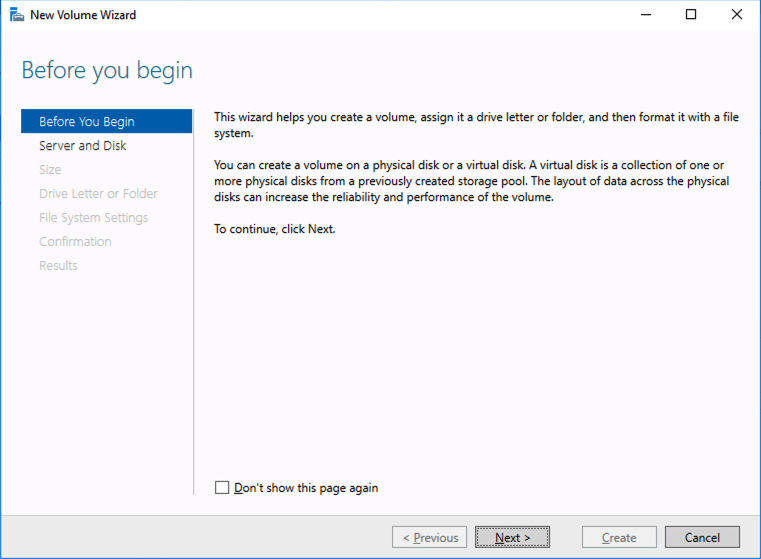
Based on the documentation found here, below are the screenshots that represent what you should see when you build your local Storage Pool on each of the two cluster nodes. Complete these steps on both servers BEFORE you build the cluster.

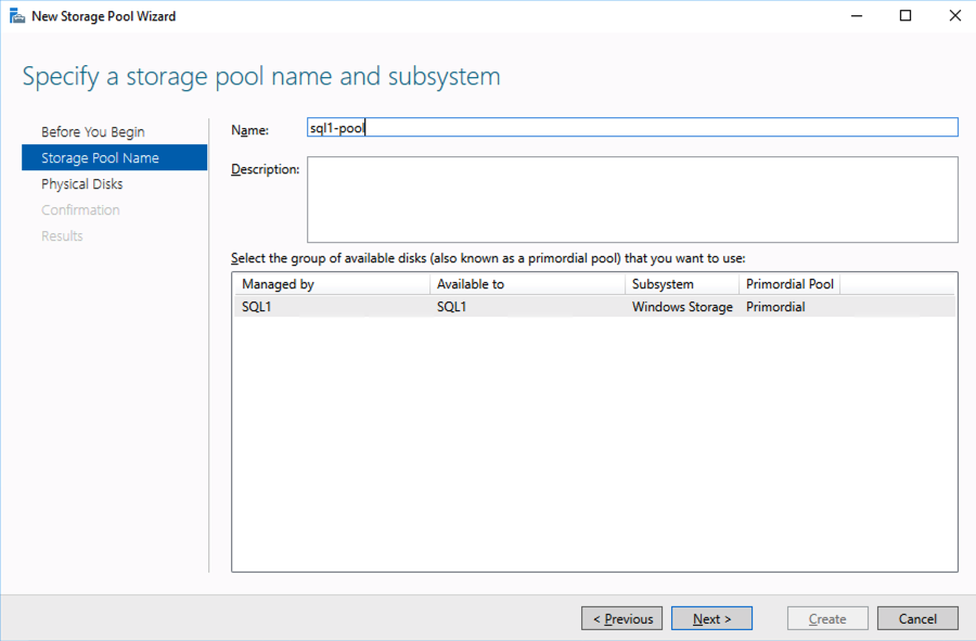
You should see the Primordial pool on both servers.
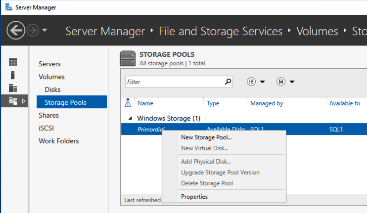
Right-click and choose New Storage Pool…
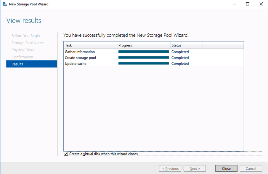
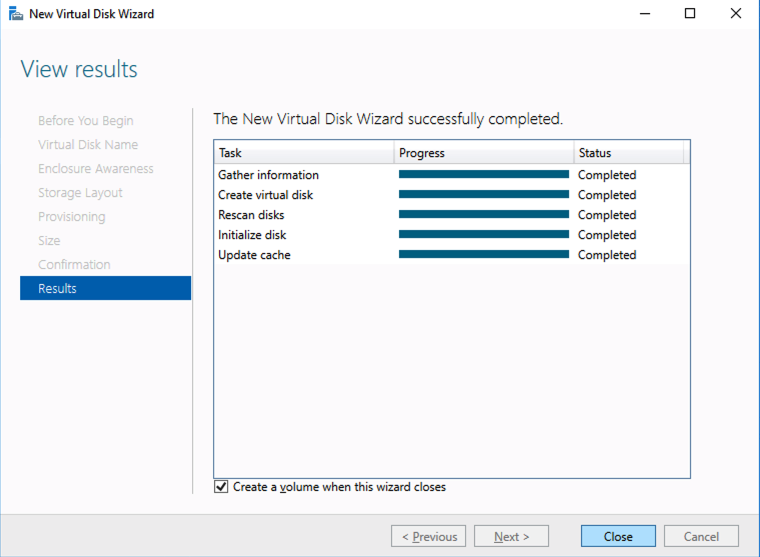
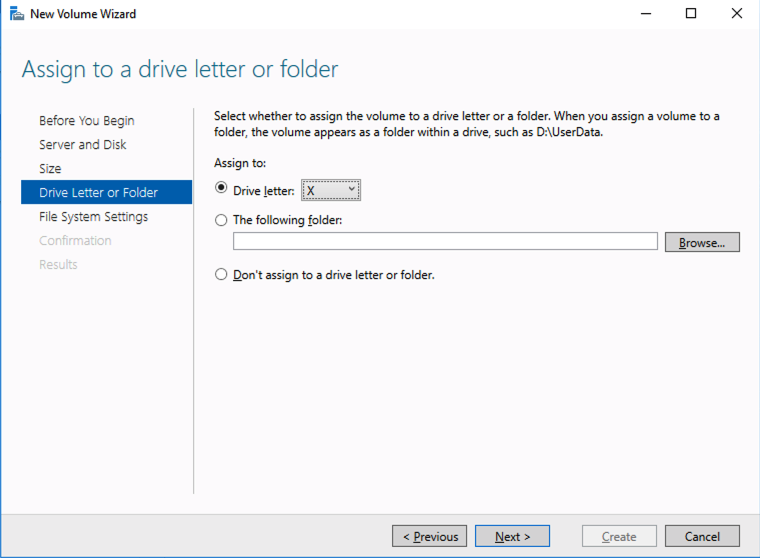
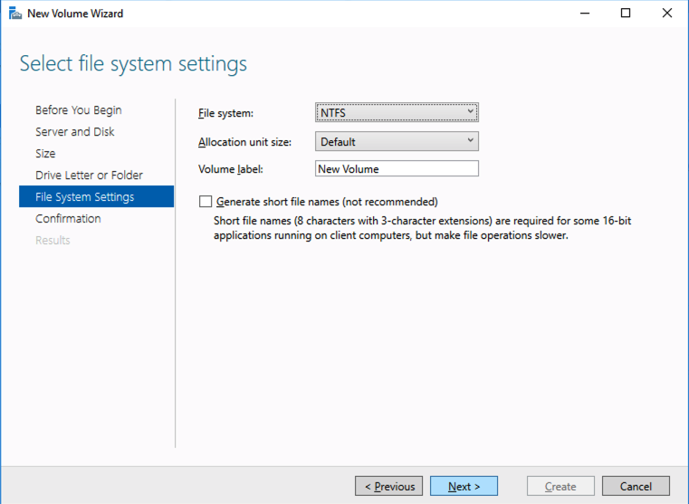
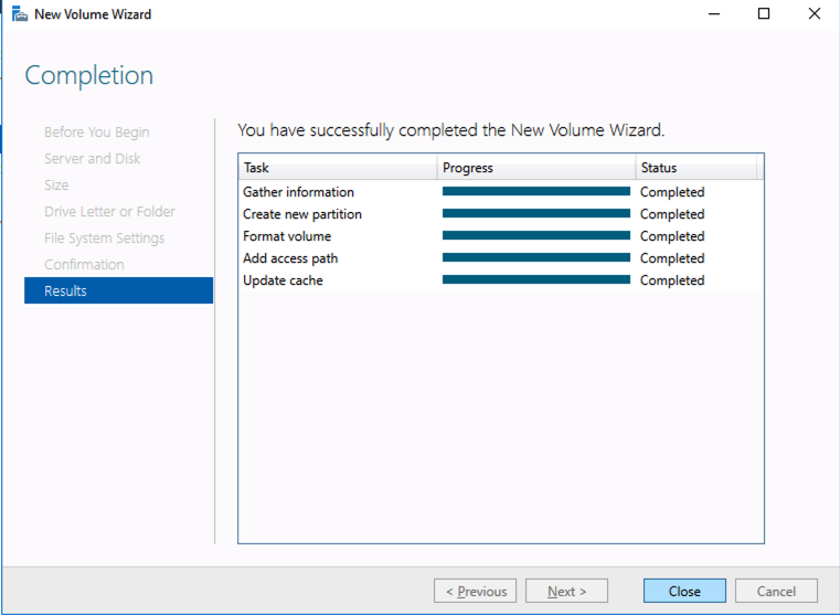
Choose Create a virtual disk when this wizard closes
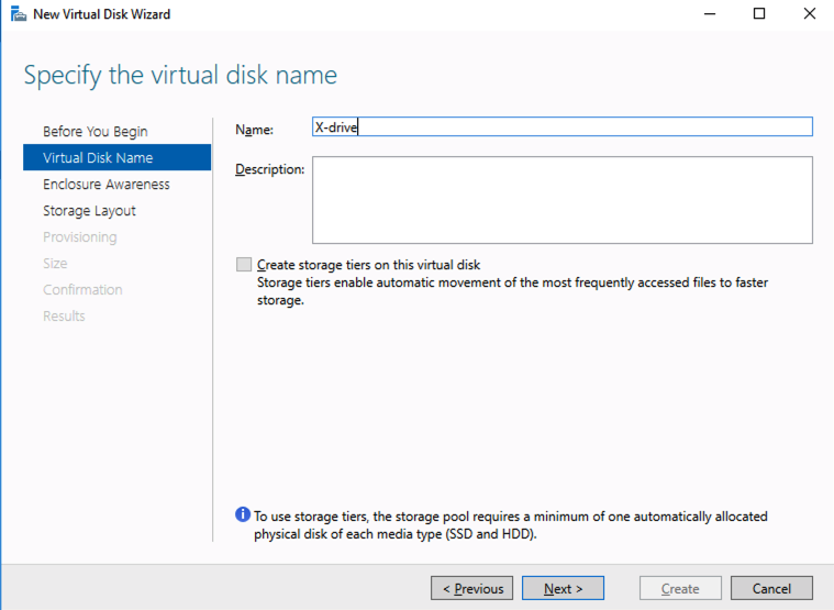
Notice here you could create storage tiers if you decided to use a combination of Standard, Premium and Ultra SSD
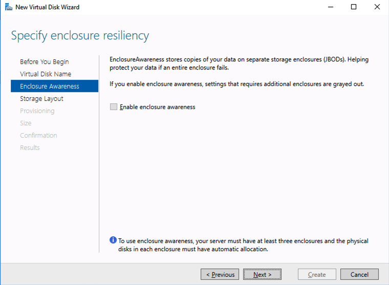
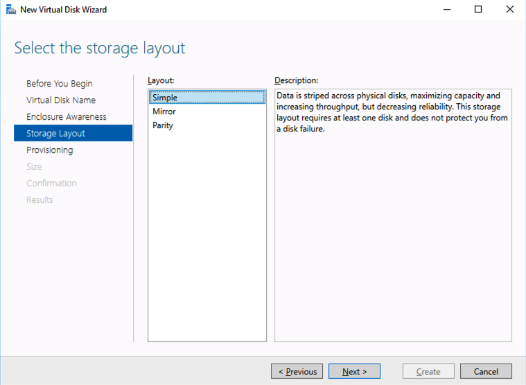
For best performance use Simple storage layout (RAID 0). Don’t be concerned about reliability since Azure Managed Disks have triple redundancy on the backend. Simple is required for optimal performance.
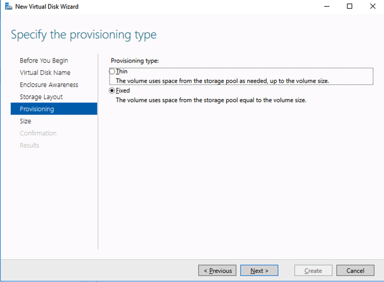
For performance purposes use Fixed provisioning. You are already paying for the full Premium disk anyway, so no need not to use it all.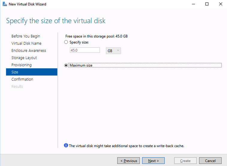
Create Your Cluster
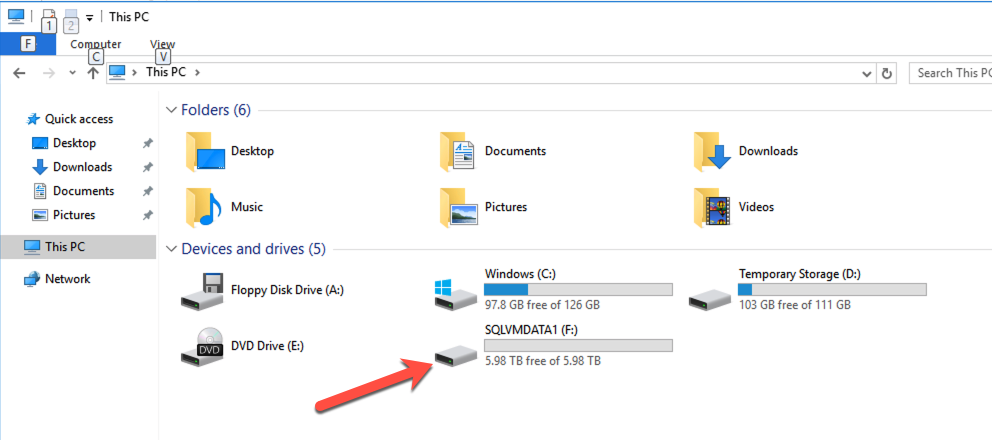
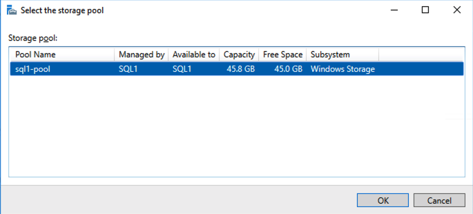
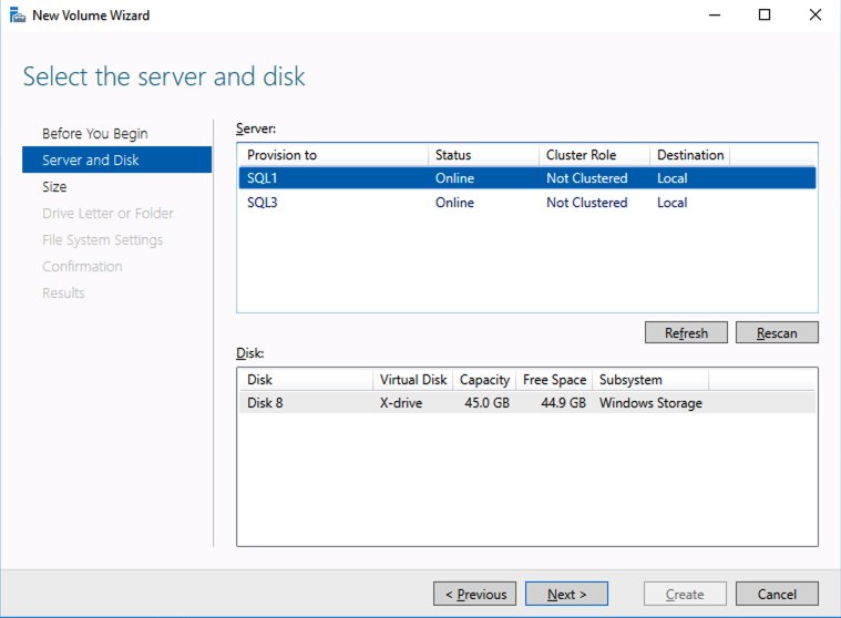
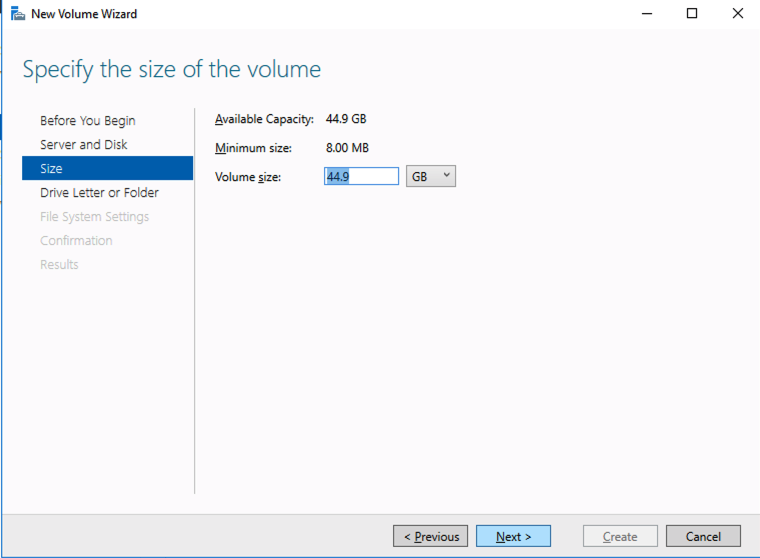
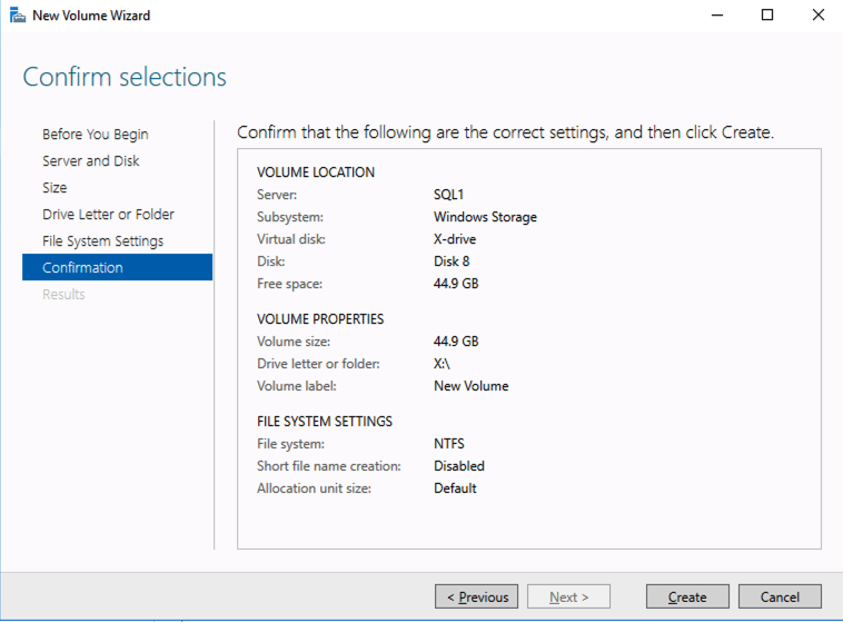
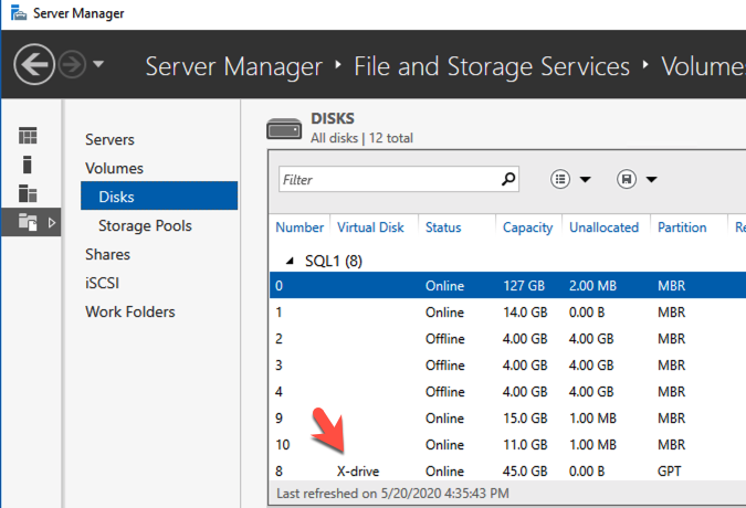
Now that each server each have their own 45 GB X drive, we are going to create the basic cluster. Creating a cluster in Azure is best done via Powershell so that we can specify a static IP address. If you do it through the GUI you will soon realize that Azure assigns your cluster IP a duplicate IP address that you will have to clean up, so don’t do that!
Here is an example Powershell code to create a new cluster.
New-Cluster -Name mycluster -NoStorage -StaticAddress 10.0.0.100 -Node sql1, sql2The output will look something like this.
PS C:\Users\dave.DATAKEEPER> New-Cluster -Name mycluster -NoStorage
-StaticAddress 10.0.0.100 -Node sql1, sql2
WARNING: There were issues while creating the clustered role that
may prevent it from starting.
For more information view the report file below.
WARNING: Report file location: C:\windows\cluster\Reports\Create Cluster
Wizard mycluster on 2020.05.20
At 16.54.45.htm

Name
----
mycluster
The warning in the report will tell you that there is no witness. Because there is no shared storage in this cluster you will have to create either a Cloud Witness or a File Share Witness. I’m not going to walk you through that process as it is pretty well documented at those links.
Don’t put this off, go ahead and create the witness now before you move to the next step!
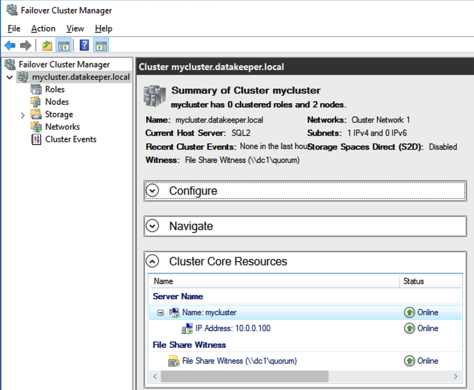
You now should have a basic 2-node cluster that looks something like this.
Configure A Load Balancer For The Cluster Core IP Address
Clusters in Azure are unique in that the Azure virtual network does not support gratuitous ARP. Don’t worry if you don’t know what that means, all you have to really know is that cluster IP addresses can’t be reached directly. Instead, you have to use an Azure Load Balancer, which redirects the client connection to the active cluster node.
There are two steps to getting a load balancer configured for a cluster in Azure. The first step is to create the load balancer. The second step is to update the cluster IP address so that it listens for the load balancer’s health probe and uses a 255.255.255.255 subnet mask which enables you to avoid IP address conflicts with the ILB.
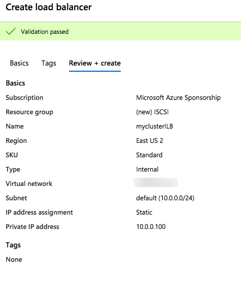
We will first create a load balancer for the cluster core IP address. Later we will edit the load balancer to also address the iSCSI cluster resource IP address that we will be created at the end of this document.
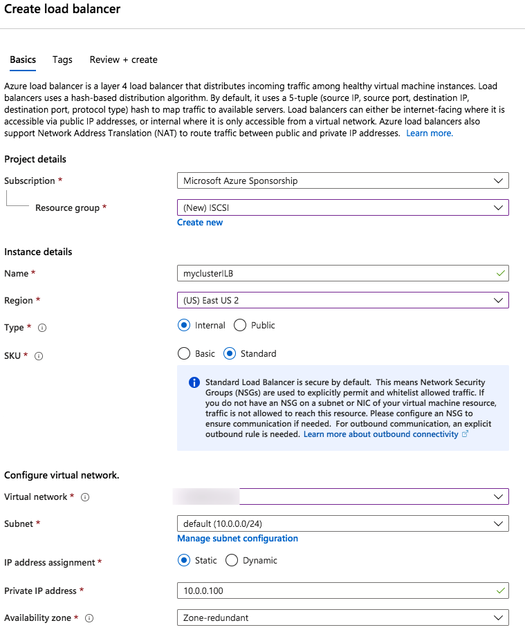
Notice that the static IP address we are using is the same address that we used to create the core cluster IP resource.
Once the load balancer is created you will edit the load balancer as shown below

Add the two cluster nodes to the backend pool
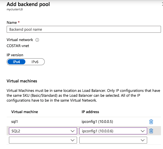
Add the two cluster nodes to the backend pool
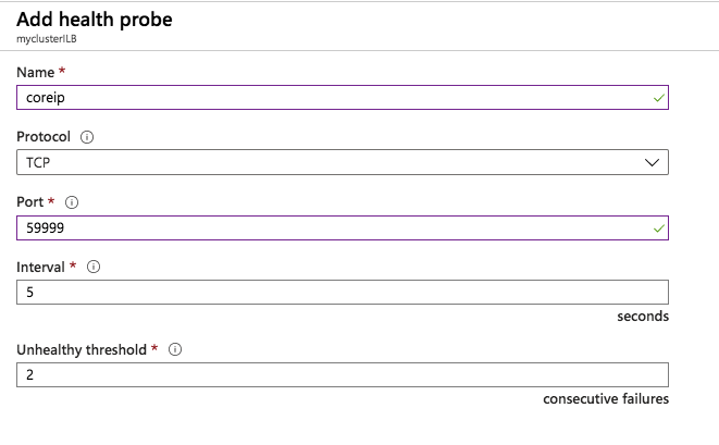
Add a health probe. In this example we use 59999 as the port. Remember that port, we will need it in the next step.
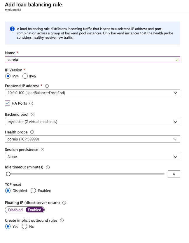
Create a new rue to redirect all HA ports, Make sure Floating IP is enabled.
STEP 2 – EDIT TO CLUSTER CORE IP ADDRESS TO WORK WITH THE LOAD BALANCER
As I mentioned earlier, there are two steps to getting the load balancer configured to work properly. Now that we have a load balancer, we have to run a Powershell script on one of the cluster nodes. The following is an example script that needs to be run on one of the cluster nodes.
$ClusterNetworkName = “Cluster Network 1”
$IPResourceName = “Cluster IP Address”
$ILBIP = “10.0.0.100”
Import-Module FailoverClusters
Get-ClusterResource $IPResourceName | Set-ClusterParameter
-Multiple @{Address=$ILBIP;ProbePort=59998;SubnetMask="255.255.255.255"
;Network=$ClusterNetworkName;EnableDhcp=0}
The important thing about the script above, besides getting all the variables correct for your environment, is making sure the ProbePort is set to the same port you defined in your load balancer settings for this particular IP address. You will see later that we will create a 2nd health probe for the iSCSI cluster IP resource that will use a different port. The other important thing is making sure you leave the subnet set at 255.255.255.255. It may look wrong, but that is what it needs to be set to.
After you run it the output should look like this.
 PS C:\Users\dave.DATAKEEPER> $ClusterNetworkName = “Cluster Network 1”
$IPResourceName = “Cluster IP Address”
$ILBIP = “10.0.0.100”
Import-Module FailoverClusters
Get-ClusterResource $IPResourceName | Set-ClusterParameter
-Multiple @{Address=$ILBIP;ProbePort=59999;SubnetMask="255.255.255.255"
;Network=$ClusterNetworkName;EnableDhcp=0}
WARNING: The properties were stored, but not all changes will take effect
until Cluster IP Address is taken offline and then online again.
You will need to take the core cluster IP resource offline and bring it back online again before it will function properly with the load balancer.
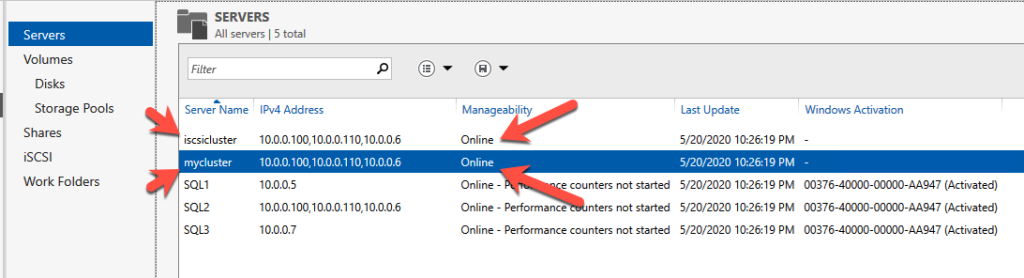
Assuming you did everything right in creating your load balancer, your Server Manager on both servers should list your cluster as Online as shown below.
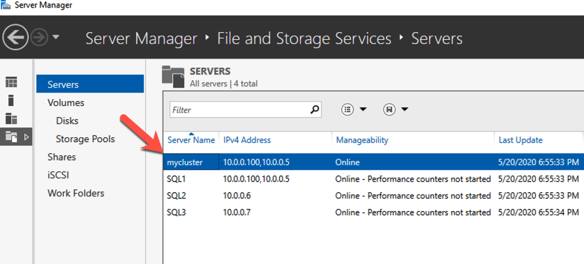
Check Server Manager on both cluster nodes. Your cluster should show as “Online” under Manageability.
Install DataKeeper
I won’t go through all the steps here, but basically at this point you are ready to install SIOS DataKeeper on both cluster nodes. It’s a pretty simple setup, just run the setup and choose all the defaults. If you run into any problems with DataKeeper it is usually one of two things. The first issue is the service account. You need to make sure the account you are using to run the DataKeeper service is in the Local Administrators Group on each node.
The second issue is in regards to firewalls. Although the DataKeeper install will update the local Windows Firewall automatically, if your network is locked down you will need to make sure the cluster nodes can communicate with each other across the required DataKeeper ports. In addition, you need to make sure the ILB health probe can reach your servers.
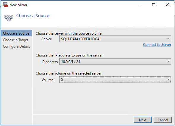
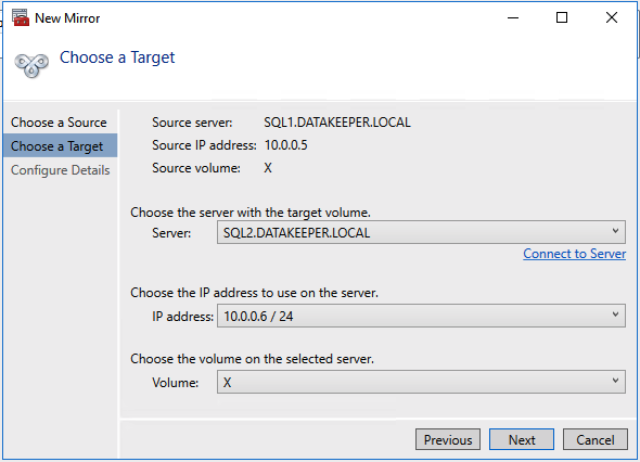
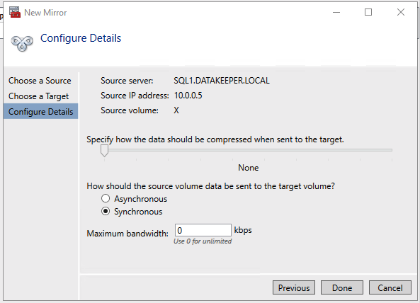
Once DataKeeper is installed you are ready to create your first DataKeeper job. Complete the following steps for each volume you want to replicate using the DataKeeper interface.
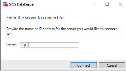
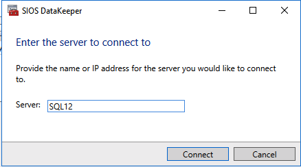
Use the DataKeeper interface to connect to both servers
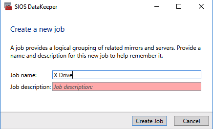
Click on create new job and give it a name
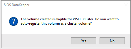
Click Yes to register the DataKeeper volume in the cluster
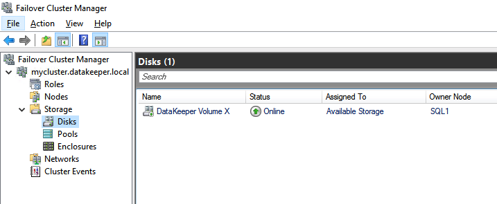
Once the volume is registered it will appear in Available Storage in Failover Cluster Manager
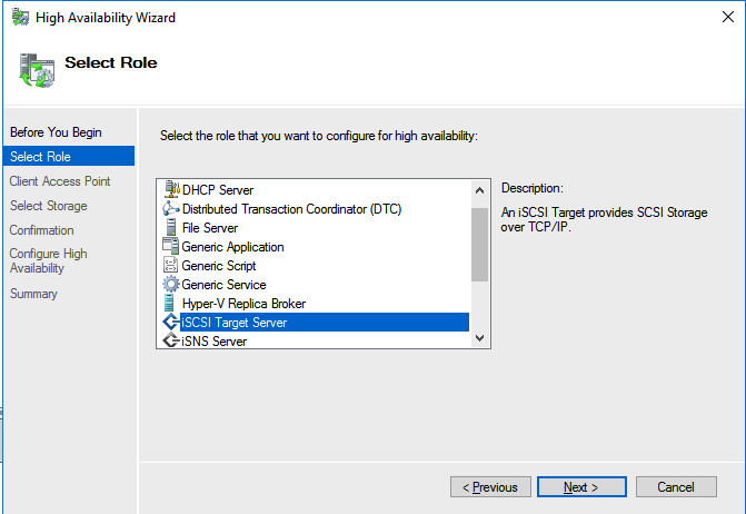
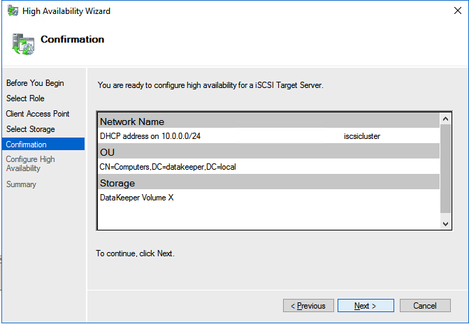
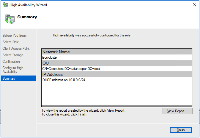
Create The ISCSI Target Server Cluster
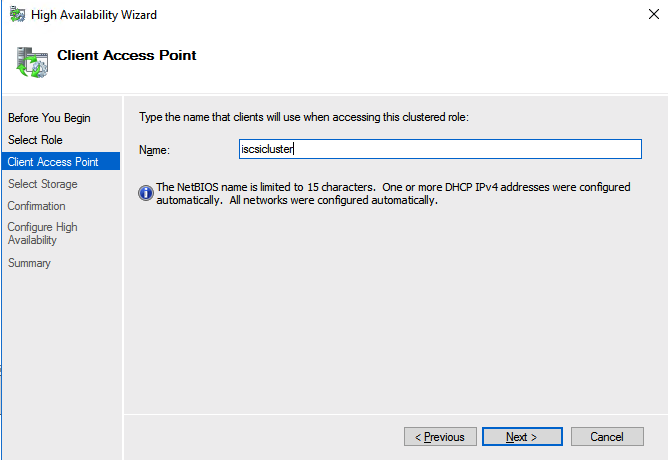
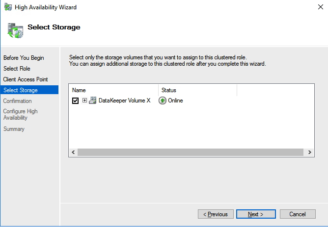
In this next step we will create the iSCSI target server role in our cluster. In an ideal world I would have a Powershell script that does all this for you, but for sake of time for now I’m just going to show you how to do it through the GUI. If you happen to write the Powershell code please feel free to share with the rest of us!
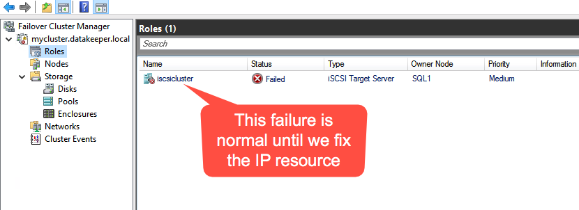
There is one problem with the GUI method. ou will wind up with a duplicate IP address in when the IP Resource is created, which will cause your cluster resource to fail until we fix it. I’ll walk through that process as well.
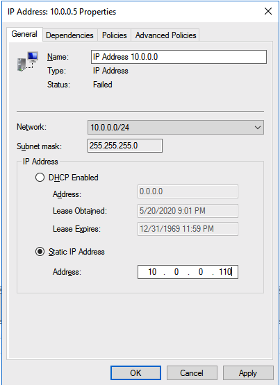
Go to the Properties of the failed IP Address resource and choose Static IP and select an IP address that is not in use on your network. Remember this address, we will use it in our next step when we update the load balancer.
You should now be able to bring the iSCSI cluster resource online.
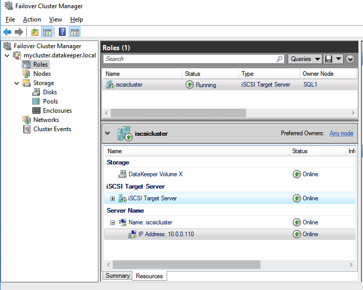
Update Load Balancer For ISCSI Target Server Cluster Resource
Like I mentioned earlier, clients can’t connect directly to the cluster IP address (10.0.0.110) we just created for the iSCSI target server cluster. We will have to update the load balancer we created earlier as shown below.
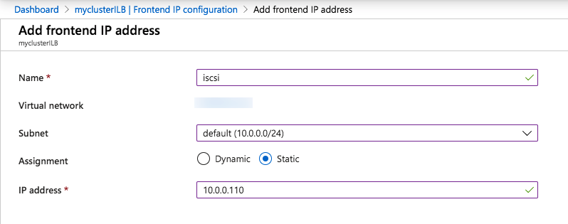
Start by adding a new frontend IP address that uses the same IP address that the iSCSI Target cluster IP resource uses.
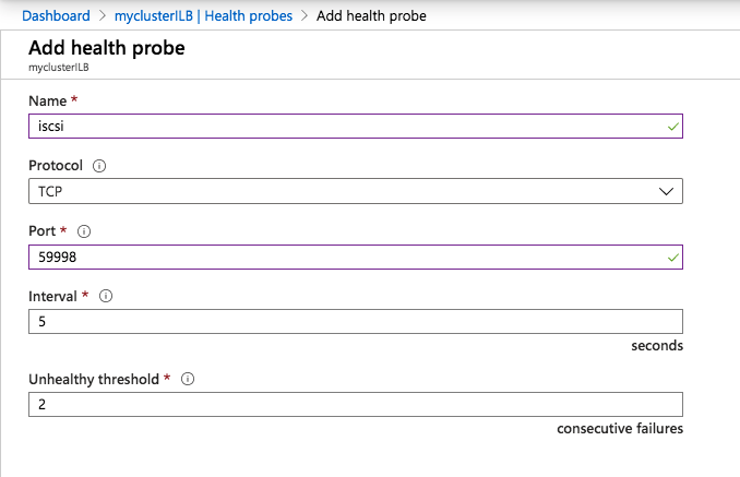
Add a second health probe on a different port. Remember this port number, we will use it again in the powershell script we run next
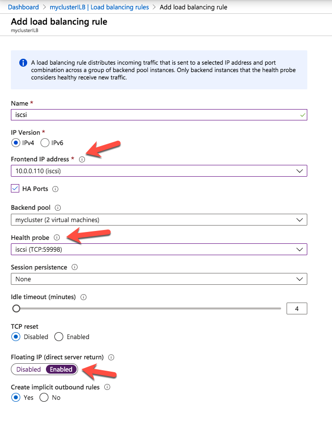
We add one more load balancing rule. Make sure to change the Frontend IP address and Health probe to use the ones we just created. Also make sure direct server return is enabled.
The final step to allow the load balancer to work is to run the following Powershell script on one of the cluster nodes. Make sure you use the new Healthprobe port, IP address and IP Resource name.
 $ClusterNetworkName = “Cluster Network 1”
$IPResourceName = “IP Address 10.0.0.0”
$ILBIP = “10.0.0.110”
Import-Module FailoverClusters
Get-ClusterResource $IPResourceName | Set-ClusterParameter
-Multiple @{Address=$ILBIP;ProbePort=59998;SubnetMask="255.255.255.255"
;Network=$ClusterNetworkName;EnableDhcp=0}
Your output should look like this.
 PS C:\Users\dave.DATAKEEPER> $ClusterNetworkName = “Cluster Network 1”
$IPResourceName = “IP Address 10.0.0.0”
$ILBIP = “10.0.0.110”
Import-Module FailoverClusters
Get-ClusterResource $IPResourceName | Set-ClusterParameter
-Multiple @{Address=$ILBIP;ProbePort=59998;SubnetMask="255.255.255.255"
;Network=$ClusterNetworkName;EnableDhcp=0}
WARNING: The properties were stored, but not all changes will take effect
until IP Address 10.0.0.0 is taken offline and then online again.
Make sure to take the resource offline and online for the settings to take effect.
Create Your Clustered ISCSI Targets
Before you begin, it is best to check to make sure Server Manager from BOTH servers can see the two cluster nodes, plus the two cluster name resources, and they both appear “Online” under manageability as shown below.
If either server has an issue querying either of those cluster names then the next steps will fail. If there is a problem I would double check all the steps you took to create the load balancer and the Powershell scripts you ran.
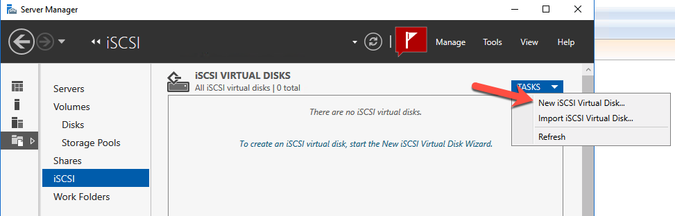
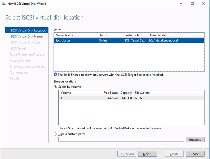
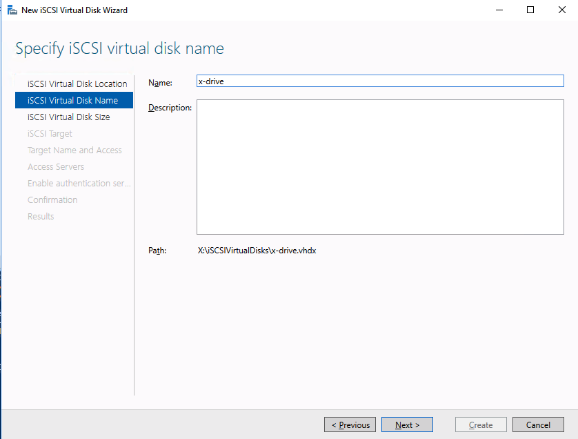
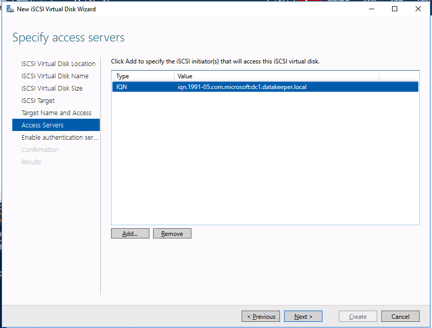
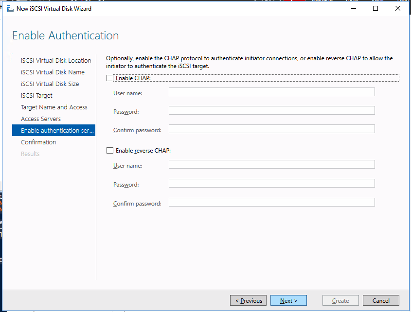
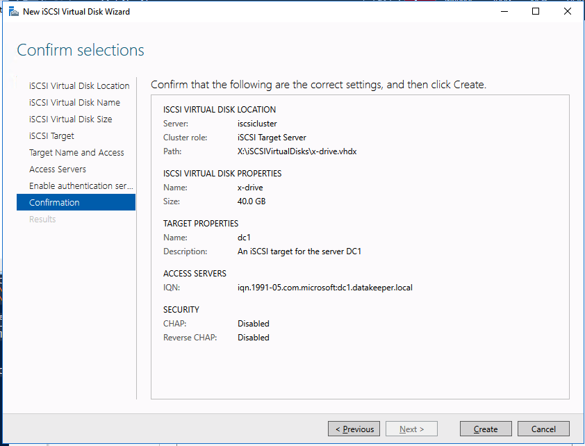
We are now ready to create our first clustered iSCSI targets. From either of the cluster nodes, follows the steps illustrated below as an example on how to create iSCSI targets.
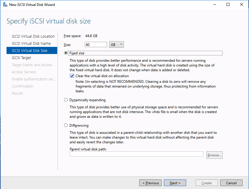
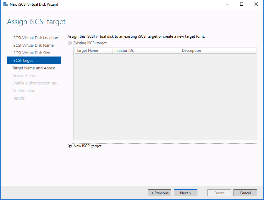
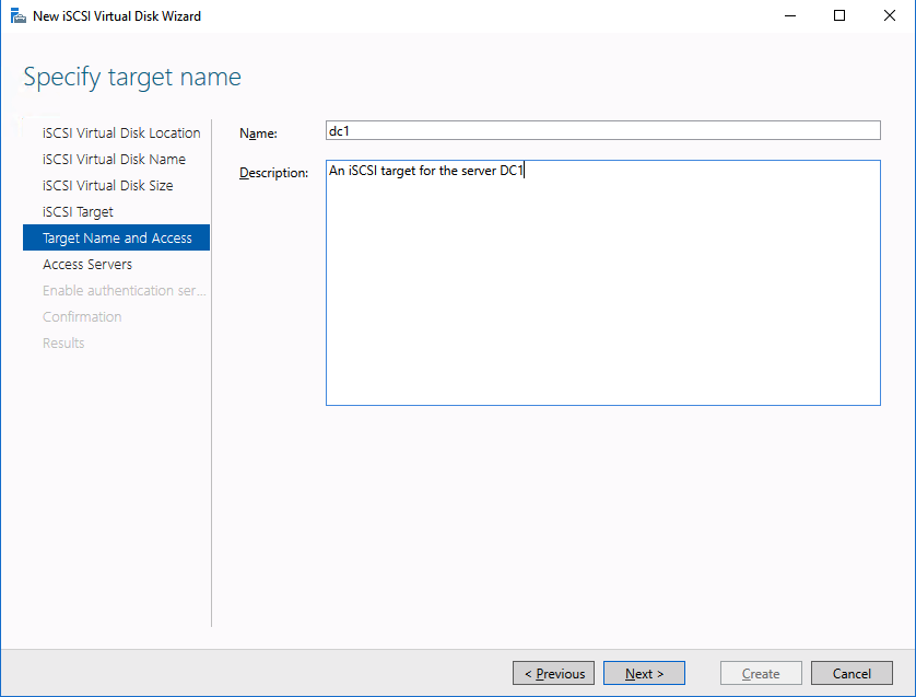
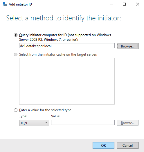
Of course assign this to whichever server or servers will be connecting to this iSSI target.
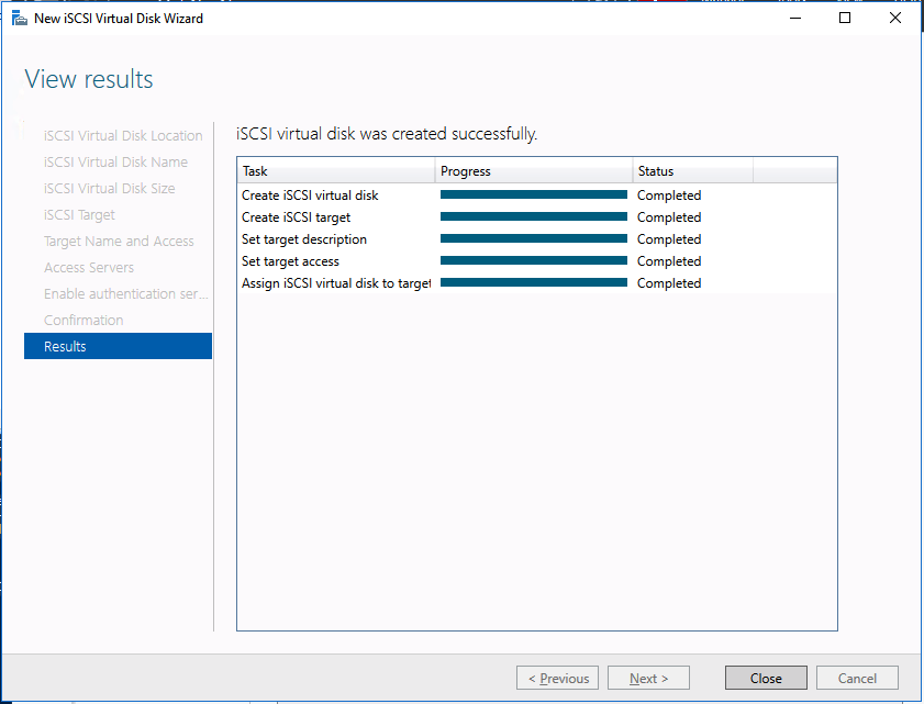
And there you have it, you now have a functioning iSCSI target server in Azure.
If you build this leave a comment and me know how you plan to use it!
Articles reproduced with permission from Clusteringwithmeremortals

 “”We got several proposals for both on-premises and cloud, and decided to migrate to Microsoft Azure with Fujitsu’s proposal of SIOS DataKeeper – that best fits our requirements,” said Akihiko Kobayashi, a System Representative.