SIOS SANless clusters

SIOS SANless clusters High-availability Machine Learning monitoring

  • Home
  • Products
    • SIOS DataKeeper for Windows
    • SIOS Protection Suite for Linux
  • News and Events
  • Clustering Simplified
  • Success Stories
  • Contact Us
  • English
  • 中文 (中国)
  • 中文 (台灣)
  • 한국어
  • Bahasa Indonesia
  • ไทย

Dynamic Utilization – More Affordable High Availability, Drive Migration To Cloud

January 18, 2019 by Jason Aw Leave a Comment

Dynamic Utilization Will Make High Availability More Affordable, Further Driving Migration to the Cloud.jpg

Dynamic Utilization Will Make High Availability More Affordable, Further Driving Migration to the Cloud

On-demand provisioning in the cloud is nothing new. What will be new are more cost-effective options for high availability and disaster recovery in hybrid and purely public cloud configurations. Such on-demand HA and DR will leverage dynamic utilization of resources spread among multiple datacenters and geographical regions, and make achieving high service levels more affordable for more applications.

Both HA and DR require redundancy to ensure reliable, rapid recovery from failures.

HA failover clustering replicates the full operational environment of the primary VM, including the CPU, memory and storage resources, in a secondary VM. All data is then also replicated in real-time to the secondary, which remains idle unless and until the primary fails. Having one or more fully redundant secondary VMs creates a cluster that is effectively in a continual state of self-test, thereby ensuring it is prepared for automatic and rapid failover.

Basic DR configurations, by contrast, lack the capabilities needed for fast failover

Consider Azure Site Recovery, for example. Microsoft positions ASR as being DR-as-a-service. And the growing DRaaS market now includes offerings from nearly a dozen providers. With ASR, primary VMs are replicated to secondaries in other Azure regions, or from on-premises instances to the Azure cloud. But the data is not replicated in real-time. The service is unable to automatically detect and failover from many causes of application-level downtime.

Underlying Issue

Many potential points of failure are simply not covered by DRaaS and other cloud availability services. In general, complete loss of service is detected. But faults due to application or OS software, as well as failures in discrete resources like network or storage are not detected. As a consequence, an application service may be disrupted-potentially for an extended period-without being detected by the cloud’s own recovery facilities.

SIOS DataKeeper and SIOS Protection Suite from SIOS Technology

When high availability is of paramount importance, comprehensive fault detection is essential to avoiding application-level downtime. This objective is readily achieved with purpose-built failover clustering technology, such as SIOS DataKeeper and SIOS Protection Suite from SIOS Technology, which is capable of automatically detecting a broad range of causes of downtime in both the software and the underlying physical and virtual resources. These software-only clusters are layered atop the cloud to provide a complete HA/DR solution that includes data replication, continuous application-level monitoring and configurable failover/failback recovery policies.

DRaaS Offerings

Failover clustering software can be configured for HA or DR alone, or for a combination of HA and DR. DR normally has a standby VM in another region in a configuration referred to as a GeoCluster. As with DRaaS offerings, WAN bandwidth limitations cause some “replication lag” for the data, and potentially some data loss under certain failure scenarios. But unlike with DRaaS, broad classes of failure are detected automatically at the cloud platform and application levels, and can be remedied immediately to assure service continuity.

While failover clustering, with its ability to minimize both recovery point and recovery time objectives (RPO/RTO), affords comprehensive service protection compared to DRaaS, the need to fully configure costly redundant and idle resources remains. Fortunately, this issue is being addressed by emerging cluster management techniques that can orchestrate a full recovery through the dynamic allocation of resources at the time of failure.

A New Approach

The standby VM, while operating in standby mode, is configured only with the resources needed to handle its minimalist role of a data replication target for the primary VM. When a failure occurs, the cluster immediately and dynamically reconfigures the standby VM with the complete complement of resources needed to deliver the level of performance required for its fully operational role of the primary VM. This dynamic utilization enables HA and DR protections to benefit from significant cost savings without sacrificing the availability and reliability benefits of clustering.

Conclusion

Both HA failover clusters and DRaaS, whether operating separately or in concert, can have roles to play in making the continuum of HA and DR protections more affordable for the full spectrum of enterprise applications-from those that can tolerate some data loss and extended periods of downtime, to those that require an RPO of zero (no data loss) and an RTO of less than five minutes under all possible failure scenarios.


About the Author

Jerry Melnick is President and CEO at SIOS Technology, where he is responsible for directing the overall corporate strategy and leading the company’s ongoing growth and expansion. He has more than 25 years of experience in the enterprise and high availability software markets. Before joining SIOS, he was CTO at Marathon Technologies where he led business and product strategy for the company’s fault tolerant solutions. His experience also includes executive positions at PPGx, Inc. and Belmont Research, where he was responsible for building a leading-edge software product and consulting business focused on supplying data warehouse and analytical tools. Jerry began his career at Digital Equipment Corporation where he led an entrepreneurial business unit that delivered highly scalable, mission critical database platforms to support enterprise-computing environments in the medical, financial and telecommunication markets. He holds a Bachelor of Science degree from Beloit College with graduate work in Computer Engineering and Computer Science at Boston University.
Filed Under: News and Events Tagged With: High Availability

Configure A Linux Failover Cluster In Amazon EC2 Without Shared Storage

December 20, 2018 by Jason Aw Leave a Comment

Step-By-Step How To Configure A Linux Failover Cluster In Microsoft Azure IaaS Without Shared Storage azure sanless

Step-By-Step: How To Configure A Linux Failover Cluster In Amazon EC2 Without Shared Storage #amazon #aws #sanless #cluster

In this step by step guide I will take you through all steps required to configure a highly available, 2-node MySQL cluster (plus witness server) in Amazon’s Elastic Compute Cloud (Amazon EC2).  The guide includes both screenshots, shell commands and code snippets as appropriate.  I assume that you are somewhat familiar with Amazon EC2 and already have an account.  If not, you can sign up today.  I’m also going to assume that you have basic linux system administration skills as well as understand basic failover clustering concepts like Virtual IPs, etc.

Disclaimer: The cloud is rapidly moving target. As such, features/screens/buttons are bound to change over time so your experience may vary slightly from what you’ll see below.  While this guide will show you how to make a MySQL database highly available, you could certainly adapt this information and process to protect other applications or databases, like SAP, Oracle, PostgreSQL, NFS file servers, and more.

These are the high level steps to create a highly available MySQL database within Amazon EC2:

  1. Create a Virtual Private Cloud (VPC)
  2. Create an Internet Gateway
  3. Create Subnets (Availability Zones)
  4. Configure Route Tables
  5. Configure Security Group
  6. Launch Instances
  7. Create Elastic IP
  8. Create Route Entry for the Virtual IP
  9. Disable Source/Dest Checking for ENI’s
  10. Obtain Access Key ID and Secret Access Key
  11. Linux OS Configuration
  12. Install EC2 API Tools
  13. Install and Configure MySQL
  14. Install and Configure Cluster
  15. Test Cluster Connectivity

Overview

This article will describe how to create a cluster within a single Amazon EC2 region.  The cluster nodes (node1, node2 and the witness server) will reside different Availability Zones for maximum availability.  This also means that the nodes will reside in different subnets.

The configuration will look like this:

AWS-Linux-MySQL

The following IP addresses will be used:

  • node1: 10.0.0.4
  • node2: 10.0.1.4
  • witness: 10.0.2.4
  • virtual/”floating” IP: 10.1.0.10

Create A Virtual Private Cloud (VPC)

First, create a Virtual Private Cloud (aka VPC). A VPC is an isolated network within the Amazon cloud that is dedicated to you.  You have full control over things like IP address blocks and subnets, route tables, security groups (i.e. firewalls), and more.  You will be launching your Azure Iaas virtual machines (VMs) into your Virtual Network.

From the main AWS dashboard, select “VPC”

vpc1

Under “Your VPCs”, make sure you have selected the proper region at the top right of the screen.  In this guide the “US West (Oregon)” region will be used, because it is a region that has 3 Availability Zones.   For more information on Regions and Availability Zones, click here

vpc2

Give the VPC a name, and specify the IP block you wish to use.  10.0.0.0/16 will be used in this guide:

vpc3

You should now see the newly created VPC on the “Your VPCs” screen:

vpc4


Create An Internet Gateway

Next, create an Internet Gateway.  This is required if you want your Instances (VMs) to be able to communicate with the internet.

On the left menu, select Internet Gateways and click the Create Internet Gateway button.  Give it a name, and create:


internet-gateway1

Next, attach the internet gateway to your VPC:

internet-gateway2

Select your VPC, and click Attach:

internet-gateway3

Create Subnets (Availability Zones)

Next, create 3 subnets.  Each subnet will reside in it’s own Availability Zone.  The 3 Instances (VMs: node1, node2, witness) will be launched into separate subnets (and therefore Availability Zones) so that the failure of an Availability Zone won’t take out multiple nodes of the cluster.

The US West (Oregon) region, aka us-west-2, has 3 availability zones (us-west-2a, us-west-2b, us-west-2c).  Create 3 subnets, one in each of the 3 availability zones.

Under VPC Dashboard, navigate to Subnets, and then Create Subnet:

subnets1

Give the first subnet a name (“Subnet1)”, select the availability zone us-west-2a, and define the network block (10.0.0.0/24):

subnets2

Repeat to create the second subnet availability zone us-west-2b:

subnets3

Repeat to create the third subnet in availability zone us-west-2c:

subnets4

Once complete, verify that the 3 subnets have been created, each with a different CIDR block, and in separate Availability Zones, as seen below:

subnets5

Configure Route Tables

Update the VPC’s route table so that traffic to the outside world is send to the Internet Gateway created in a previous step.  From the VPC Dashboard, select Route Tables.   Go to the Routes tab, and by default only one route will exist which allows traffic only within the VPC.

Click Edit:

route-table1


Add another route:

route-table2

The Destination of the new route will be “0.0.0.0/0” (the internet) and for Target, select your Internet Gateway.  Then click Save:

route-table3


Next, associate the 3 subnets with the Route Table.   Click the “Subnet Associations” tab, and Edit:

route-table4

Check the boxes next to all 3 subnets, and Save:

route-table5

Verify that the 3 subnets are associated with the main route table:

route-table6


Later, we will come back and update the Route Table once more, defining a route that will allow traffic to communicate with the cluster’s Virtual IP, but this needs to be done AFTER the linux Instances (VMs) have been created.

Configure Security Group

Edit the Security Group (a virtual firewall) to allow incoming SSH and VNC traffic.  Both will later be used to configure the linux instances as well as installation/configuration of the cluster software.

On the left menu, select “Security Groups” and then click the “Inbound Rules” tab.  Click Edit:

security-group1


Add rules for both SSH (port 22) and VNC.  VNC generally uses ports in the 5900, depending on how you configure it, so for the purposes of this guide, we will open the 5900-5910 port range.  Configure accordingly based on your VNC setup:

security-group2


Launch Instances

We will be provisioning 3 Instances (Virtual Machines) in this guide.  The first two VMs (called “node1” and “node2”) will function as cluster nodes with the ability to bring the MySQL database and it’s associated resources online.  The 3rd VM will act as the cluster’s witness server for added protection against split-brain.

To ensure maximum availability, all 3 VMs will be deployed into different Availability Zones within a single region.  This means each instance will reside in a different subnet.

Go to the main AWS dashboard, and select EC2:

launch-instance1

Create “node1”

Create your first instance (“node1”).  Click Launch Instance:

launch-instance2

Select your linux distribution.  The cluster software used later supports RHEL, SLES, CentOS and Oracle Linux.  In this guide we will be using RHEL 7.X:

launch-instance3

Size your instance accordingly.  For the purposes of this guide and to minimize cost, t2.micro size was used because it’s free tier eligible.  See here for more information on instance sizes and pricing.

launch-instance4

Next, configure instance details.  IMPORTANT: make sure to launch this first instance (VM) into “Subnet1“, and define an IP address valid for the subnet (10.0.0.0/24) – below 10.0.0.4 is selected because it’s the first free IP in the subnet.  NOTE: .1/.2/.3 in any given subnet in AWS is reserved and can’t be used.

launch-instance5

Next, add an extra disk to the cluster nodes (this will be done on both “node1” and “node2”).  This disk will store our MySQL databases and the later be replicated between nodes.

Note: You do NOT need to add an extra disk to the “witness” node.  Only “node1” and “node2”.

Add New Volume, and enter in the desired size:

launch-instance6


Define a Tag for the instance, Node1:

launch-instance7

Associate the instance with the existing security group, so the firewall rules created previous will be active:

launch-instance8

Click Launch:

launch-instance9

IMPORTANT:  If this is the first instance in your AWS environment, you’ll need to create a new key pair.  The private key file will need to be stored in a safe location as it will be required when you SSH into the linux instances

launch-instance10

Create “node2”

Repeat the steps above to create your second linux instance (node2).  Configure it exactly like Node1.  However, make sure that you deploy it into “Subnet2” (us-west-2b availability zone).  The IP range for Subnet2 is 10.0.1.0/24, so an IP of 10.0.1.4 is used here:

launch-instance11

Make sure to add a 2nd disk to Node2 as well.  It should be the same exact size as the disk you added to Node1:

launch-instance12

Give the second instance a tag…. “Node2”:

launch-instance13

Create “witness”

Repeat the steps above to create your third linux instance (witness).  Configure it exactly like Node1&Node2, EXCEPT you DON’T need to add a 2nd disk, since this instance will only act as a witness to the cluster, and won’t ever bring MySQL online.

Make sure that you deploy it into “Subnet3” (us-west-2c availability zone).  The IP range for Subnet2 is 10.0.2.0/24, so an IP of 10.0.2.4 is used here:

launch-instance14

Note: default disk configuration is fine for the witness node.  A 2nd disk is NOT required:

launch-instance15

Tag the witness node:

launch-instance16

It may take a little while for your 3 instances to provision.  Once complete, you’ll see then listed as running in your EC2 console:

launch-instance17

Create Elastic IP

Next, create an Elastic IP, which is a public IP address that will be used to connect into you instance from the outside world.  Select Elastic IPs in the left menu, and then click “Allocate New Address”:

elastic-ip1

Select the newly created Elastic IP, right-click, and select “Associate Address”:

elastic-ip2

Associate this Elastic IP with Node1:

elastic-ip3

Repeat this for the other two instances if you want them to have internet access or be able to SSH/VNC into them directly.

Create Route Entry for the Virtual IP

At this point all 3 instances have been created, and the route table will need to be updated one more time in order for the cluster’s Virtual IP to work.  In this multi-subnet cluster configuration, the Virtual IP needs to live outside the range of the CIDR allocated to your VPC.

Define a new route that will direct traffic to the cluster’s Virtual IP (10.1.0.10) to the primary cluster node (Node1)

From the VPC Dashboard, select Route Tables, click Edit.  Add a route for “10.1.0.10/32” with a destination of Node1:

route-table-after-instance-creation

Disable Source/Dest Checking for ENI’s

Next, disable Source/Dest Checking for the Elastic Network Interfaces (ENI) of your cluster nodes. This is required in order for the instances to accept network packets for the virtual IP address of the cluster.

Do this for all ENIs.

Select “Network Interfaces”, right-click on an ENI, and select “Change Source/Dest Check”.

disable-source-dest-check1

Select “Disabled“:

disable-source-dest-check2

Obtain Access Key ID and Secret Access Key

Later in the guide, the cluster software will use the AWS Command Line Interface (CLI) to manipulate a route table entry for the cluster’s Virtual IP to redirect traffic to the active cluster node.  In order for this to work, you will need to obtain an Access Key ID and Secret Access Key so that the AWS CLI can authenticate properly.

In the top-right of the EC2 Dashboard, click on your name, and underneath select “Security Credentials” from the drop-down:

access-key1


Expand the “Access Keys (Access Key ID and Secret Access Key)” section of the table, and click “Create New Access Key”.  Download Key File and store the file in a safe location.

access-key2

Linux OS Configuration

Connect to the linux instance(s):

To connect to your newly created linux instances (via SSH), right click on the instance and select “Connect”.  This will display the instructions for connecting to the instance.  You will need the Private Key File you created/downloaded in a previous step:

connect1

Example:

connect2

Here is where we will leave the EC2 Dashboard for a little while and get our hands dirty on the command line, which as a Linux administrator you should be used to by now.

You aren’t given the root password to your Linux VMs in AWS (or the default “ec2-user” account either), so once you connect, use the “sudo” command to gain root privileges:

$sudo su -

Edit /etc/hosts

Unless you have already have a DNS server setup, you’ll want to create host file entries on all 3 servers so that they can properly resolve each other by name

Add the following lines to the end of your /etc/hosts file:

10.0.0.4    node1
10.0.1.4    node2
10.0.2.4    witness
10.1.0.10   mysql-vip

Disable SELinux

Edit /etc/sysconfig/linux and set “SELINUX=disabled”:

# vi /etc/sysconfig/selinux

# This file controls the state of SELinux on the system.
# SELINUX= can take one of these three values:
#     enforcing - SELinux security policy is enforced.
#     permissive - SELinux prints warnings instead of enforcing.
#     disabled - No SELinux policy is loaded.
SELINUX=disabled
# SELINUXTYPE= can take one of these two values:
#     targeted - Targeted processes are protected,
#     mls - Multi Level Security protection.
SELINUXTYPE=targeted

Set Hostnames

By default, these Linux instances will have a hostname that is based upon the server’s IP address, something like “ip-10-0-0-4.us-west-2.compute.internal”

You might notice that if you attempt to modify the hostname the “normal” way (i.e. editing /etc/sysconfig/network, etc), after each reboot, it reverts back to the original!!  I found a great thread in the AWS discussion forums that describes how to actually get hostnames to remain static after reboots.

Details here:  https://forums.aws.amazon.com/message.jspa?messageID=560446

Comment out modules that set hostname in “/etc/cloud/cloud.cfg” file. The following modules can be commented out using #.

# - set_hostname
# - update_hostname

Next, also change your hostname in /etc/hostname.

Reboot Cluster Nodes

Reboot all 3 instances so that SELinux is disabled, and the hostname changes take effect.

Install and Configure VNC (and related packages)

In order to access the GUI of our linux servers, and to later install and configure our cluster, install VNC server, as well as a handful of other required packages (cluster software needs the redhat-lsb and patch rpms).

# yum groupinstall “X Window System”
# yum groupinstall “Server with GUI”
# yum install tigervnc-server xterm wget unzip patch redhat-lsb
# vncpasswd

For RHEL 7.x/CentOS7.x:

The following URL is a great guide to getting VNC Server running on RHEL 7 / CentOS 7:

https://www.digitalocean.com/community/tutorials/how-to-install-and-configure-vnc-remote-access-for-the-gnome-desktop-on-centos-7

Note:  This example configuration runs VNC on display 2 (:2, aka port 5902) and as root (not secure).  Adjust accordingly!

# cp /lib/systemd/system/vncserver@.service /etc/systemd/system/vncserver@:2.service
# vi /etc/systemd/system/vncserver@:2.service


[Service]
Type=forking
# Clean any existing files in /tmp/.X11-unix environment
ExecStartPre=/bin/sh -c '/usr/bin/vncserver -kill %i > /dev/null 2>&1 || :'
ExecStart=/sbin/runuser -l root -c "/usr/bin/vncserver %i -geometry 1024x768"
PIDFile=/root/.vnc/%H%i.pid
ExecStop=/bin/sh -c '/usr/bin/vncserver -kill %i > /dev/null 2>&1 || :'


# systemctl daemon-reload
# systemctl enable vncserver@:2.service
# vncserver :2 -geometry 1024x768

For RHEL/CentOS 6.x systems:

# vi /etc/sysconfig/vncservers

      VNCSERVERS="2:root"
      VNCSERVERARGS[2]="-geometry 1024x768"

# service vncserver start
# chkconfig vncserver on

Open a VNC client, and connect to the <ElasticIP:2>.  If you can’t get it, it’s likely your linux firewall is in the way.  Either open the VNC port we are using here (port 5902), or for now, disable the firewall (NOT RECOMMENDED FOR PRODUCTION ENVIRONMENTS):

# systemctl stop firewalld
# systemctl disable firewalld


Partition and Format the “data” disk

When the linux instances were launched, and extra disk was added to each cluster node to store the application data we will be protecting.  In this case it happens to be MySQL databases.

The second disk should appear as /dev/xvdb.  You can run the “fdisk -l” command to verify.  You’ll see that /dev/xvda (OS) is already being used.

# fdisk -l

Disk /dev/xvda: 10.7 GB, 10737418240 bytes, 20971520 sectors
Units = sectors of 1 * 512 = 512 bytes
Sector size (logical/physical): 512 bytes / 512 bytes
I/O size (minimum/optimal): 512 bytes / 512 bytes
Disk label type: gpt

#         Start          End    Size  Type            Name
1         2048         4095      1M  BIOS boot parti
2         4096     20971486     10G  Microsoft basic
Disk /dev/xvdb: 2147 MB, 2147483648 bytes, 4194304 sectors
Units = sectors of 1 * 512 = 512 bytes
Sector size (logical/physical): 512 bytes / 512 bytes
I/O size (minimum/optimal): 512 bytes / 512 bytes


Here I will create a partition (/dev/xvdb1), format it, and mount it at the default location for MySQL, which is /var/lib/mysql.  Perform the following steps on BOTH “node1” and “node2”:

# fdisk /dev/xvdb
Welcome to fdisk (util-linux 2.23.2).

Changes will remain in memory only, until you decide to write them.
Be careful before using the write command.

Device does not contain a recognized partition table
Building a new DOS disklabel with disk identifier 0x8c16903a.

Command (m for help): n
Partition type:
   p   primary (0 primary, 0 extended, 4 free)
   e   extended
Select (default p): p
Partition number (1-4, default 1): 1
First sector (2048-4194303, default 2048): <enter>
Using default value 2048
Last sector,  sectors or  size{K,M,G} (2048-4194303, default 4194303): <enter>
Using default value 4194303
Partition 1 of type Linux and of size 2 GiB is set

Command (m for help): w
The partition table has been altered!

Calling ioctl() to re-read partition table.
Syncing disks.

# mkfs.ext4 /dev/xvdb1
# mkdir /var/lib/mysql

On node1, mount the filesystem:

# mount /dev/xvdb1 /var/lib/mysql

Install EC2 API Tools

The EC2 API Tools (EC2 CLI) must be installed on each of the cluster nodes, so that the cluster software can later manipulate Route Tables, enabling connectivity to the Virtual IP.

The following URL is an excellent guide to setting this up.:

http://docs.aws.amazon.com/AWSEC2/latest/CommandLineReference/set-up-ec2-cli-linux.html

Here are the key steps:

Download, unzip, and move the CLI tools to the standard location (/opt/aws):

# wget http://s3.amazonaws.com/ec2-downloads/ec2-api-tools.zip
# unzip ec2-api-tools.zip
# mv ec2-api-tools-1.7.5.1/ /opt/aws/
# export EC2_HOME="/opt/aws"

If java isn’t already installed (run “which java” to check), install it:

# yum install java-1.8.0-openjdk

example (Based on default config of RHEL 7.2 system.  Adjust accordingly)

# export JAVA_HOME="/usr/lib/jvm/java-1.8.0-openjdk-1.8.0.71-2.b15.el7_2.x86_64/jre/"

You’ll need your AWS Access Key and AWS Secret Key.  Keep these values handy, because they will be needed later during cluster setup too! Refer to the following URL for more information:

https://console.aws.amazon.com/iam/home?#security_credential

# export AWS_ACCESS_KEY=your-aws-access-key-id
# export AWS_SECRET_KEY=your-aws-secret-key

Test CLI utility functionality:

# /opt/aws/bin/ec2-describe-regions

REGION           eu-west-1       ec2.eu-west-1.amazonaws.com
REGION           ap-southeast-1           ec2.ap-southeast-1.amazonaws.com
REGION           ap-southeast-2           ec2.ap-southeast-2.amazonaws.com
REGION           eu-central-1    ec2.eu-central-1.amazonaws.com
REGION           ap-northeast-2            ec2.ap-northeast-2.amazonaws.com
REGION           ap-northeast-1            ec2.ap-northeast-1.amazonaws.com
REGION           us-east-1         ec2.us-east-1.amazonaws.com
REGION           sa-east-1         ec2.sa-east-1.amazonaws.com
REGION           us-west-1        ec2.us-west-1.amazonaws.com
REGION           us-west-2        ec2.us-west-2.amazonaws.com


Install and Configure MySQL

Next, install install the MySQL packages, initialize a sample database, and set “root” password for MySQL.  In RHEL7.X, the MySQL packages have been replaced with the MariaDB packages.

On “node1”:

# yum install mariadb mariadb-server
# mount /dev/xvdb1 /var/lib/mysql
# /usr/bin/mysql_install_db --datadir="/var/lib/mysql/" --user=mysql
# mysqld_safe --user=root --socket=/var/lib/mysql/mysql.sock --port=3306 --datadir=/var/lib/mysql --log &
#
# # NOTE: This next command allows remote connections from ANY host.  NOT a good idea for production!
# echo “update user set Host='%' where Host='node1'; flush privileges | mysql mysql
#
# #Set MySQL's root password to 'SIOS'
# echo "update user set Password=PASSWORD('SIOS') where User='root'; flush privileges" | mysql mysql

Create a MySQL configuration file. We will place this on the data disk  (that will later be replicated – /var/lib/mysql/my.cnf).  Example:

# vi /var/lib/mysql/my.cnf

[mysqld]
datadir=/var/lib/mysql
socket=/var/lib/mysql/mysql.sock
pid-file=/var/run/mariadb/mariadb.pid
user=root
port=3306
# Disabling symbolic-links is recommended to prevent assorted security risks
symbolic-links=0
 
[mysqld_safe]
log-error=/var/log/mariadb/mariadb.log
pid-file=/var/run/mariadb/mariadb.pid 
 
[client]
user=root
password=SIOS

Move the original MySQL configuration file aside, if it exists:

# mv /etc/my.cnf /etc/my.cnf.orig

On “node2”:

On “node2”, you ONLY need to install the MariaDB/MySQL packages.  The other steps aren’t required:

[root@node2 ~]# yum install mariadb mariadb-server

Install and Configure the Cluster

At this point, we are ready to install and configure our cluster.  SIOS Protection Suite for Linux (aka SPS-Linux) will be used in this guide as the clustering technology.  It provides both high availability failover clustering features (LifeKeeper) as well as real-time, block level data replication (DataKeeper) in a single, integrated solution.  SPS-Linux enables you to deploy a “SANLess” cluster, aka a “shared nothing” cluster meaning that cluster nodes don’t have any shared storage, as is the case with EC2 Instances.

Install SIOS Protection Suite for Linux

Perform the following steps on ALL 3 VMs (node1, node2, witness):

Download the SPS-Linux installation image file (sps.img) and and obtain either a trial license or purchase permanent licenses.  Contact SIOS for more information.

You will loopback mount it and run the “setup” script inside, as root (or first “sudo su -” to obtain a root shell)

For example:

# mkdir /tmp/install
# mount -o loop sps.img /tmp/install
# cd /tmp/install
# ./setup

During the installation script, you’ll be prompted to answer a number of questions.  You will hit Enter on almost every screen to accept the default values.  Note the following exceptions:

  • On the screen titled “High Availability NFS” you may select “n” as we will not be creating a highly available NFS server
  • Towards the end of the setup script, you can choose to install a trial license key now, or later. We will install the license key later, so you can safely select “n” at this point
  • In the final screen of the “setup” select the ARKs (Application Recovery Kits, i.e. “cluster agents”) you wish to install from the list displayed on the screen.
    • The ARKs are ONLY required on “node1” and “node2”.  You do not need to install on “witness”
    • Navigate the list with the up/down arrows, and press SPACEBAR to select the following:
      • lkDR – DataKeeper for Linux
      • lkSQL – LifeKeeper MySQL RDBMS Recovery Kit
    • This will result in the following additional RPMs installed on “node1” and “node2”:
      • steeleye-lkDR-9.0.2-6513.noarch.rpm
      • steeleye-lkSQL-9.0.2-6513.noarch.rpm

Install Witness/Quorum package

The Quorum/Witness Server Support Package for LifeKeeper (steeleye-lkQWK) combined with the existing failover process of the LifeKeeper core allows system failover to occur with a greater degree of confidence in situations where total network failure could be common. This effectively means that failovers can be done while greatly reducing the risk of “split-brain” situations.

Install the Witness/Quorum rpm on all 3 nodes (node1, node2, witness):

# cd /tmp/install/quorum
# rpm -Uvh steeleye-lkQWK-9.0.2-6513.noarch.rpm

On ALL 3 nodes (node1, node2, witness), edit /etc/default/LifeKeeper, set

NOBCASTPING=1

On ONLY the Witness server (“witness”), edit /etc/default/LifeKeeper, set

WITNESS_MODE=off/none

Install the EC2 Recovery Kit Package

SPS-Linux provides specific features that allow resources to failover between nodes in different availability zones and regions. Here, the EC2 Recovery Kit (i.e. cluster agent) is used to manipulate Route Tables so that connections to the Virtual IP are routed to the active cluster node.

Install the EC2 rpm (node1, node2):

# cd /tmp/install/amazon
# rpm -Uvh steeleye-lkECC-9.0.2-6513.noarch.rpm

Install a License key

On all 3 nodes, use the “lkkeyins” command to install the license file that you obtained from SIOS:

# /opt/LifeKeeper/bin/lkkeyins <path_to_file>/<filename>.lic

Start LifeKeeper

On all 3 nodes, use the “lkstart” command to start the cluster software:

# /opt/LifeKeeper/bin/lkstart

Set User Permissions for LifeKeeper GUI

On all 3 nodes, create a new linux user account (i.e. “tony” in this example).  Edit /etc/group and add the “tony” user to the “lkadmin” group to grant access to the LifeKeeper GUI.  By default only “root” is a member of the group, and we don’t have the root password here:

# useradd tony
# passwd tony
# vi /etc/group

lkadmin:x:1001:root,tony

Open the LifeKeeper GUI

Make a VNC connection to the Elastic IP (Public IP) address of node1.  Based on the VNC  configuration from above, you would connect to <Public_IP>:2 using the VNC password you specified earlier.  Once logged in, open a terminal window and run the LifeKeeper GUI using the following command:

# /opt/LifeKeeper/bin/lkGUIapp &

You will be prompted to connect to your first cluster node (“node1”).  Enter the linux userid and password specified during VM creation:

lk-gui-connect1

Next, connect to both “node2” and “witness” by clicking the “Connect to Server” button highlighted in the following screenshot:

lk-gui-connect2

You should now see all 3 servers in the GUI, with a green checkmark icon indicating they are online and healthy:

lk-gui-connect3

Create Communication Paths

Right-click on “node1” and select Create Comm Path

comm path1

Select BOTH “node2” and “witness” and then follow the wizard.  This will create comm paths between:

  • node1 & node2
  • node1 & witness

comm path2

A comm path still needs to be created between node2 & witness.   Right click on “node2” and select Create Comm Path.  Follow the wizard and select “witness” as the remote server:

comm path3

At this point the following comm paths have been created:

  • node1 <—> node2
  • node1 <—> witness
  • node2 <—> witness

The icons in front of the servers have changed from a green “checkmark” to a yellow “hazard sign”.  This is because we only have a single communication path between nodes.

If the VMs had multiple NICs (information on creating Azure VMs with multiple NICs can be found here, but won’t be covered in this article), you would create redundant comm paths between each server.

comm path4

To remove the warning icons, go to the View menu and de-select “Comm Path Redundancy Warning”:

comm path5

Result:

comm path6

Verify Communication Paths

Use the “lcdstatus” command to view the state of cluster resources.  Run the following commands to verify that you have correctly created comm paths on each node to the other two servers involved:

# /opt/LifeKeeper/bin/lcdstatus -q -d node1

MACHINE  NETWORK ADDRESSES/DEVICE   STATE     PRIO

node2    TCP     10.0.0.4/10.0.1.4  ALIVE        1

witness  TCP     10.0.0.4/10.0.2.4  ALIVE        1

#/opt/LifeKeeper/bin/lcdstatus -q -d node2

MACHINE  NETWORK ADDRESSES/DEVICE   STATE     PRIO

node1    TCP     10.0.1.4/10.0.0.4  ALIVE        1

witness  TCP     10.0.1.4/10.0.2.4  ALIVE        1

#/opt/LifeKeeper/bin/lcdstatus -q -d witness

MACHINE  NETWORK ADDRESSES/DEVICE   STATE     PRIO

node1    TCP     10.0.2.4/10.0.0.4  ALIVE        1

node2    TCP     10.0.2.4/10.0.1.4  ALIVE        1

Create a Data Replication cluster resource (i.e. Mirror)

Next, create a Data Replication resource to replicate the /var/lib/mysql partition from node1 (source) to node2 (target).  Click the “green plus” icon to create a new resource:

data replication1

Follow the wizard with these selections:

Please Select Recovery Kit:  Data Replication
Switchback Type: intelligent
Server: node1
Hierarchy Type: Replicate Exiting Filesystem
Existing Mount Point: /var/lib/mysql
Data Replication Resource Tag: datarep-mysql
File System Resource Tab: /var/lib/mysql
Bitmap File: (default value)
Enable Asynchronous Replication:  No

After the resource has been created, the “Extend” (i.e. define backup server) wizard will appear.  Use the following selections:

Target Server: node2
Switchback Type: Intelligent
Template Priority: 1
Target Priority: 10
Target Disk: /dev/xvdb1
Data Replication Resource Tag: datarep-mysql
Bitmap File: (default value)
Replication Path: 10.0.0.4/10.0.1.4
Mount Point: /var/lib/mysql
Root Tag: /var/lib/mysql

The cluster will look like this:

data replication2

Create Virtual IP

Next, create a Virtual IP cluster resource.  Click the “green plus” icon to create a new resource:

virtual ip1

Follow the wizard with to create the IP resource with these selections:

Select Recovery Kit: IP
Switchback Type: Intelligent
IP Resource: 10.1.0.10
Netmask: 255.255.255.0
Network Interface: eth0
IP Resource Tag: ip-10.1.0.10

Extend the IP resource with these selections:

Switchback Type: Intelligent
Template Priority: 1
Target Priority: 10
IP Resource: 10.1.0.10
Netmask: 255.255.255.0
Network Interface: eth0
IP Resource Tag: ip-10.1.0.10

The cluster will now look like this, with both Mirror and IP resources created:

cluster-after-mirror-and-vip

Configure a Ping List for the IP resource

By default, SPS-Linux monitors the health of IP resources by performing a broadcast ping.  In many virtual and cloud environments, broadcast pings don’t work.  In a previous step, we set “NOBCASTPING=1” in /etc/default/LifeKeeper to turn off broadcast ping checks. Instead, we will define a ping list.  This is a list of IP addresses to be pinged during IP health checks for this IP resource.   In this guide, we will add the witness server (10.0.2.4) to our ping list.

Right click on the IP resource (ip-10.1.0.10) and select Properties:

aws-ping-list1

You will see that initially, no ping list is configured for our 10.1.0.0 subnet.   Click “Modify Ping List”:

aws-ping-list2

Enter “10.0.2.4” (the IP address of our witness server), click “Add address” and finally click “Save List”:

aws-ping-list3

You will be returned to the IP properties panel, and can verify that 10.0.2.4 has been added to the ping list.  Click OK to close the window:

aws-ping-list4

Create the MySQL resource hierarchy

Next, create a MySQL cluster resource.  The MySQL resource is responsible for stopping/starting/monitoring of your MySQL database.

Before creating MySQL resource, make sure the database is running.  Run “ps -ef | grep sql” to check.

If it’s running, great – nothing to do.  If not, start the database back up:

# mysqld_safe --user=root --socket=/var/lib/mysql/mysql.sock --port=3306 --datadir=/var/lib/mysql --log &

To create, click the “green plus” icon to create a new resource:

Follow the wizard with to create the IP resource with these selections:

Select Recovery Kit: MySQL Database
Switchback Type: Intelligent
Server: node1
Location of my.cnf: /var/lib/mysql
Location of MySQL executables: /usr/bin
Database Tag: mysql

Extend the IP resource with the following selections:

Target Server: node2
Switchback Type: intelligent
Template Priority: 1
Target Priority: 10

As a result, your cluster will look as follows.  Notice that the Data Replication resource was automatically moved underneath the database (dependency automatically created) to ensure it’s always brought online before the database:

aws-after-mysql-resource1

Create An EC2 Resource To Manage The Route Tables Upon Failover

SPS-Linux provides specific features that allow resources to failover between nodes in different availability zones and regions. Here, the EC2 Recovery Kit (i.e. cluster agent) is used to manipulate Route Tables so that connections to the Virtual IP are routed to the active cluster node.

To create, click the “green plus” icon to create a new resource:

Follow the wizard with to create the EC2 resource with these selections:

Select Recovery Kit: Amazon EC2
Switchback Type: Intelligent
Server: node1
EC2 Home: /opt/aws
EC2 URL: ec2.us-west-2.amazonaws.com
AWS Access Key: (enter Access Key obtained earlier)
AWS Secret Key: (enter Secret Key obtained earlier)
EC2 Resource Type: RouteTable (Backend cluster)
IP Resource: ip-10.1.0.10
EC2 Resource Tag: ec2-10.1.0.10

Extend the IP resource with the following selections:

Target Server: node2
Switchback Type: intelligent
Template Priority: 1
Target Priority: 10
EC2 Resource Tag: ec2-10.1.0.10

The cluster will look like this.  Notice how the EC2 resource is underneath the IP resource:

aws-after-ec2-resource1

Create a Dependency between the IP resource and the MySQL Database resource

Create a dependency between the IP resource and the MySQL Database resource so that they failover together as a group.  Right click on the “mysql” resource and select “Create Dependency”:

create-dependency1

On the following screen, select the “ip-10.1.0.10” resource as the dependency.  Click Next and continue through the wizard:

create-dependency2

At this point the SPS-Linux cluster configuration is complete.  The resource hierarchy will look as follows:

create-dependency3

Test Cluster Connectivity

At this point, all of our Amazon EC2 and Cluster configurations are complete!

Cluster resources are currently active on node1:

create-dependency3

Test connectivity to the cluster from the witness server (or another linux instance if you have one)  SSH into the witness server, “sudo su -” to gain root access.   Install the mysql client if needed:

[root@witness ~]# yum -y install mysql

Test MySQL connectivity to the cluster:

[root@witness ~]# mysql --host=10.1.0.10 mysql -u root -p

Execute the following MySQL query to display the hostname of the active cluster node:

MariaDB [mysql]> select @@hostname;
 ------------ 
| @@hostname |
 ------------ 
| node1      |
 ------------ 
1 row in set (0.00 sec)
MariaDB [mysql]>

Using LifeKeeper GUI, failover from Node1 -> Node2″.  Right click on the mysql resource underneath node2, and select “In Service…”:

aws-failover1


After failover has completed, re-run the MySQL query.  You’ll notice that the MySQL client has detected that the session was lost (during failover) and automatically reconnects:

Execute the following MySQL query to display the hostname of the active cluster node, verifying that now “node2” is active:

MariaDB [mysql]> select @@hostname;
ERROR 2006 (HY000): MySQL server has gone away
No connection. Trying to reconnect...
Connection id:    12
Current database: mysql
 ------------ 
| @@hostname |
 ------------ 
| node2      |
 ------------ 
1 row in set (0.53 sec)
MariaDB [mysql]>


Likes these step by step guides to Configure A Linux Failover Cluster In Amazon EC2 Without Shared Storage, read more here

Reproduced with permission from Linuxclustering

Filed Under: Clustering Simplified Tagged With: AWS, High Availability, Linux failover clusters, MySQL

Linux failover cluster in Microsoft Azure IaaS without shared storage

December 19, 2018 by Jason Aw Leave a Comment

Step-By-Step: How To Configure A Linux Failover Cluster In Microsoft Azure IaaS Without Shared Storage #azure #sanless

In this step by step guide I will take you through all steps required to configure a highly available, 2-node MySQL cluster (plus witness server) in Microsoft Azure IaaS (Infrastructure as a Service).  The guide includes both screenshots, shell commands and code snippets as appropriate.  I assume that you are somewhat familiar with Microsoft Azure and already have an Azure account with an associated subscription.  If not, you can sign up for a free account today.  I’m also going to assume that you have basic linux system administration skills as well as understand basic failover clustering concepts like Virtual IPs, etc.

Disclaimer: Azure is a rapidly moving target.  It’s getting better and better every day!  As such, features/screens/buttons are bound to change over time so your experience may vary slightly from what you’ll see below.  While this guide will show you how to make a MySQL database highly available, you could certainly adapt this information and process to protect other applications or databases, like SAP, Oracle, PostgreSQL, NFS file servers, and more.

These are the high level steps to create a highly available MySQL database within Microsoft Azure IaaS:

  1. Create a Resource Group
  2. Create a Virtual Network
  3. Create a Storage Account
  4. Create Virtual Machines in an Availability Set
  5. Set VM Static IP Addresses
  6. Add a Data Disk to cluster nodes
  7. Create Inbound Security Rule to allow VNC access
  8. Linux OS Configuration
  9. Install and Configure MySQL
  10. Install and Configure Cluster
  11. Create an Internal Load Balancer
  12. Test Cluster Connectivity

Overview

This article will inform of the steps to configure Linux Failover Cluster In Microsoft Azure IaaS Without Shared Storage. It will describe how to create a cluster within a single Azure region.  The cluster nodes (node1, node2 and the witness server) will reside in an Availability Set (3 different Fault Domains and Update Domains), thanks to the new Azure Resource Manager (ARM). We will be creating all resources using the new Azure Resource Manager.

The configuration will look like this:

The following IP addresses will be used:

  • node1: 10.0.0.4
  • node2: 10.0.0.5
  • witness: 10.0.0.6
  • virtual/”floating” IP: 10.0.0.99
  • MySQL port: 3306

Create a Resource Group

First, create a Resource Group.  Your resource group will end up containing all of the various objects related to our cluster deployment: virtual machines, virtual network, storage account, etc.  Here we will call our newly created Resource Group “cluster-resources”.


Be mindful when selecting your region.  All of your resources will need to reside within the same region.  Here, we’ll be deploying everything into the “West US” region:

Create a Virtual Network (VNet)

Creating a Virtual Network  would be your next step in connfiguring Linux Failover Cluster In Microsoft Azure IaaS Without Shared Storage. A Virtual Network is an isolated network within the Azure cloud that is dedicated to you.  You have full control over things like IP address blocks and subnets, routing, security policies (i.e. firewalls), DNS settings, and more.  You will be launching your Azure Iaas virtual machines (VMs) into your Virtual Network.

Make sure you select Resource Manager as the deployment model anytime you are given the option:

Give your new Virtual Network a name (“virtual-network”) and make sure you select the resource group that was created in the previous step (“cluster-resources”).  Your Virtual Network needs to reside in the same region your Resource Group.  We will leave the IP Address and Subnet values as default.


Create a Storage Account

Before you provision any Virtual Machines, you’ll need to create a Storage Account where they will be stored.

Again, make sure you select Resource Manager as the deployment model anytime you are given the option:

Next, give your new storage account a name.  The storage account name must be unique across *ALL* of Azure.  (Every object that you store in Azure Storage has a unique URL address. The storage account name forms the subdomain of that address.)  In this example I call my storage account “linuxclusterstorage” but you’ll need to select something different as you setup your own.

Select a storage Type based on your requirements and budget.  For the purposes of this guide, I selected “Standard-LRS” (i.e. Locally Redundant) to minimize cost.
Make sure your new Storage Account is added to the Resource Group you created in Step 1 (“cluster-resources”)  in the same Location (“West US” in this example):

Create Virtual Machines in an Availability Set

We will be provisioning 3 Virtual Machines in this guide.  The first two VMs (I’ll call them “node1” and “node2”) will function as cluster nodes with the ability to bring the MySQL database and it’s associated resources online.  The 3rd VM will act as the cluster’s witness server for added protection against split-brain.

To ensure maximum availability, all 3 VMs will be added to the same Availability Set, ensuring that they will end up in different Fault Domains and Update Domains.

Create “node1” VM

Create your first VM (“node1”).  In this guide we will be using CentOS 6.X:

Make sure you use the Resource Manager deployment model.  It should be selected by default:

Give the VM a hostname (“node1”) and username/password that will later be used to SSH into the system.  Make sure you add this VM to your Resource Group (“cluster-resources”) and that it resides in the same region as all of your other resources:

Next, choose your instance size.  For more information on the various instance sizes available, click here.

For the purposes of this guide, I’m using “A3 Standard” for Node1 and Node2, to minimize cost since this won’t be running a production workload.  I used an even smaller “A1 Standard” size for the witness server.  Select the instance size that makes most sense for you.

If you want to be able to connect into the VM from the outside world, set a Public IP address.  I did this so I can later SSH and VNC into the system

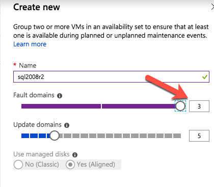
IMPORTANT: By default, your VM won’t be added to an Availability Set.  On the Settings screen during make sure you create a new Availability Set, we’ll call “cluster-availability-set”.  Azure Resource Manager (ARM) allows your to create Availability Sets with 3 Fault Domains.  The default values here are fine:

Review your VM properties and click OK to create your first VM:


Create “node2” and “witness” VMs

Repeat the steps above twice to create two more VMs.  I created another “A3 Standard” size VM called “node2” and an “A1 Standard” size VM called “witness”.

The only difference here is that you’ll be ADDING these VMs to the Availability Set (“cluster-availability-set”) we just created:

It may take a little while for your 3 VMs to provision.  Once complete, you’ll see your VMs listed on the Virtual Machines screen within your Azure Portal:

Set VM Static IP Addresses

The VMs will be set with the following IP addresses:

  • node1: 10.0.0.4
  • node2: 10.0.0.5
  • witness: 10.0.0.6

Repeat this step for each VM.  Select your VM and edit the Network Interfaces

Select the network interface associated with the VM, and edit IP addresses.  Select “Static” and specify the desired IP address:

Add a Data Disk to cluster nodes

Next, we will need to add a extra disk to of our cluster nodes (“node1” and “node2”).  This disk will store our MySQL databases and the later be replicated between nodes.

Note: You do NOT need to add an extra disk to the “witness” node.  Only “node1” and “node2”.

Edit your VM, select Disks and then attach a new disk:

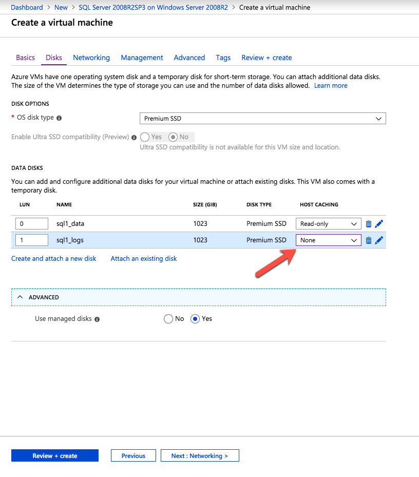
Select a disk type (Standard or Premium SSD)  and size based on your workload.  Here I create a 10GB Standard disk on both of my cluster nodes.  As far as Host caching goes, “None” or “Read only” caching is fine. I do not recommend using “Read/Write” as there is potential for data loss:

Create Inbound Security Rule to allow VNC access

If your VM is part of a Network Security Group (NSG), which by default it likely is unless you disabled it during VM creation, the only port open in the “Azure firewall” is SSH (port 22).  Later in the guide, I’ll be using VNC to access the desktop of “node1” and configure the cluster using a GUI.  Create an Inbound Security Rule to open up VNC access.  In this guide port 5902 is used.  Adjust this according based on your VNC configuration.

Virtual Machines -> (select node1) -> Network interfaces -> (select NIC) -> Network security group -> (select the NSG) -> Inbound security rules -> Add


Linux OS Configuration

Here is where we will leave the Azure Portal for a little while and get our hands dirty on the command line, which as a Linux administrator you should be used to by now.  You aren’t given the root password to your Linux VMs in Azure, so once you login as the user specified during VM creation, use the “sudo” command to gain root privileges:

$sudo su -

Edit /etc/hosts

Unless you have already have a DNS server setup, you’ll want to create host file entries on all 3 servers so that they can properly resolve each other by name

Add the following lines to the end of your /etc/hosts file:

10.0.0.4    node1
10.0.0.5    node2
10.0.0.6    witness
10.0.0.99   mysql-vip

Disable SELinux

Edit /etc/sysconfig/linux and set “SELINUX=disabled”:

# vi /etc/sysconfig/selinux

# This file controls the state of SELinux on the system.
# SELINUX= can take one of these three values:
#     enforcing - SELinux security policy is enforced.
#     permissive - SELinux prints warnings instead of enforcing.
#     disabled - No SELinux policy is loaded.
SELINUX=disabled
# SELINUXTYPE= can take one of these two values:
#     targeted - Targeted processes are protected,
#     mls - Multi Level Security protection.
SELINUXTYPE=targeted

Configure iptables so that cluster the Virtual IP will work

IMPORTANT: In order to get connectivity to the cluster Virtual IP to work, and also monitoring of the IP resource, a few iptables rules need to be setup.  Note: 10.0.0.99 is the Virtual IP we’ll be using in our cluster, and 3306 is the default port used my MySQL.

On node1 (10.0.0.4), run the following commands:

# iptables --flush
# iptables -t nat -A PREROUTING -p tcp --dport 3306 -j DNAT 
--to-destination 10.0.0.99:3306
# iptables -t nat -A POSTROUTING -p icmp -s 10.0.0.99 -j SNAT 
--to-source 10.0.0.4
# service iptables save
# chkconfig iptables on

On Node2 (10.0.0.5), run the following commands:

# iptables --flush
# iptables -t nat -A PREROUTING -p tcp --dport 3306 -j DNAT 
--to-destination 10.0.0.99:3306
# iptables -t nat -A POSTROUTING -p icmp -s 10.0.0.99 -j SNAT 
--to-source 10.0.0.5
# service iptables save
# chkconfig iptables on

Install and Configure VNC (and related packages)

In order to access the GUI of our linux servers, to later configure our cluster, install VNC server on your cluster node.  In my setup I only did this on “node1”

# yum install tigervnc-server xterm
# vncpasswd
# vi /etc/sysconfig/vncservers

      VNCSERVERS="2:root"
      VNCSERVERARGS[2]="-geometry 1024x768"

# service vncserver start
# chkconfig vncserver on

Test connectivity by opening a VNC client on your laptop/desktop, and connecting to the Public IP of your cluster node

Reboot Cluster Nodes

Reboot your cluster nodes so that SELinux is disabled, and the 2nd disk you previously added is detected. Only “node1” and “node2” need to be rebooted.

Partition and Format the “data” disk

In Step 6 of this guide (“Add a Data Disk to cluster nodes”) we did just that….added an extra disk to each cluster node to store the application data we will be protecting.  In this case it happens to be MySQL databases.

In Azure IaaS, Linux Virtual Machines use the following arrangement for disks:

  • /dev/sda – OS disk
  • /dev/sdb – temporary disk
  • /dev/sdc – 1st data disk
  • /dev/sdd – 2nd data disk
  • …
  • /dev/sdj – 8th data disk

The disk we added in Step 6 of this guide should appear as /dev/sdc.  You can run the “fdisk -l” command to verify.  You’ll see that /dev/sda (OS) and /dev/sdb (temporary) already have disk partitions and are being used.

# fdisk -l

Disk /dev/sdb: 306.0 GB, 306016419840 bytes
255 heads, 63 sectors/track, 37204 cylinders
Units = cylinders of 16065 * 512 = 8225280 bytes
Sector size (logical/physical): 512 bytes / 512 bytes
I/O size (minimum/optimal): 512 bytes / 512 bytes
Disk identifier: 0xd3920649

Device Boot      Start         End      Blocks   Id  System
/dev/sdb1   *           1       37205   298842112   83  Linux

Disk /dev/sdc: 10.7 GB, 10737418240 bytes
255 heads, 63 sectors/track, 1305 cylinders
Units = cylinders of 16065 * 512 = 8225280 bytes
Sector size (logical/physical): 512 bytes / 512 bytes
I/O size (minimum/optimal): 512 bytes / 512 bytes
Disk identifier: 0x00000000

Disk /dev/sda: 32.2 GB, 32212254720 bytes
255 heads, 63 sectors/track, 3916 cylinders
Units = cylinders of 16065 * 512 = 8225280 bytes
Sector size (logical/physical): 512 bytes / 512 bytes
I/O size (minimum/optimal): 512 bytes / 512 bytes
Disk identifier: 0x000c23d3

Device Boot      Start         End      Blocks   Id  System
/dev/sda1   *           1        3789    30432256   83  Linux
/dev/sda2            3789        3917     1024000   82  Linux swap / Solaris


Here I will create a partition (/dev/sdc1), format it, and mount it at the default location for MySQL, which is /var/lib/mysql.  Perform the following steps on BOTH “node1” and “node2”:

# fdisk /dev/sdc
Command (m for help): n
Command action
e   extended
p   primary partition (1-4)
p
Partition number (1-4): 1
First cylinder (1-1305, default 1): <enter>
Using default value 1
Last cylinder,  cylinders or  size{K,M,G} (1-1305, default 1305): <enter>
Using default value 1305
 
Command (m for help): w
The partition table has been altered!
Calling ioctl() to re-read partition table.
Syncing disks.
[root@node1 ~]#

# mkfs.ext4 /dev/sdc1
# mkdir /var/lib/mysql

On node1, mount the filesystem:

# mount /dev/sdc1 /var/lib/mysql

Install And Configure MySQL

Next, install install the MySQL packages, initialize a sample database, and set “root” password for MySQL.

On “node1”:

# yum -y install mysql mysql-server
# /usr/bin/mysql_install_db --datadir="/var/lib/mysql/" --user=mysql
# mysqld_safe --user=root --socket=/var/lib/mysql/mysql.sock --port=3306 
--datadir=/var/lib/mysql --log &
#
# # NOTE: This next command allows remote connections from ANY host.  
NOT a good idea for production!
# echo “update user set Host='%' where Host='node1'; flush privileges | mysql mysql
#
# #Set MySQL's root password to 'SIOS'
# echo "update user set Password=PASSWORD('SIOS') where User='root'; flush privileges" 
| mysql mysql

Create a MySQL configuration file. We will place this on the data disk  (that will later be replicated – /var/lib/mysql/my.cnf).  Example:

# vi /var/lib/mysql/my.cnf

[mysqld]
datadir=/var/lib/mysql
socket=/var/lib/mysql/mysql.sock
pid-file=/var/lib/mysql/mysqld.pid
user=root
port=3306
# Disabling symbolic-links is recommended to prevent assorted security risks
symbolic-links=0
 
[mysqld_safe]
log-error=/var/log/mysqld.log
pid-file=/var/run/mysqld/mysqld.pid
 
[client]
user=root
password=SIOS

Delete the original MySQL configuration file, located in /etc, if it exists:

# rm /etc/my.cnf

On “node2”:

On “node2”, you ONLY need to install the MySQL packages.  The other steps aren’t required:

[root@node2 ~]# yum -y install mysql mysql-server

Install and Configure the Cluster

At this point, we are ready to install and configure our cluster.  SIOS Protection Suite for Linux (aka SPS-Linux) will be used in this guide as the clustering technology.  It provides both high availability failover clustering features (LifeKeeper) as well as real-time, block level data replication (DataKeeper) in a single, integrated solution.  SPS-Linux enables you to deploy a “SANLess” cluster, aka a “shared nothing” cluster meaning that cluster nodes don’t have any shared storage, as is the case with Azure VMs.

Install SIOS Protection Suite for Linux

Perform the following steps on ALL 3 VMs (node1, node2, witness):

Download the SPS-Linux installation image file (sps.img) and and obtain either a trial license or purchase permanent licenses.  Contact SIOS for more information.

You will loopback mount it and run the “setup” script inside, as root (or first “sudo su -” to obtain a root shell)

For example:

# mkdir /tmp/install
# mount -o loop sps.img /tmp/install
# cd /tmp/install
# ./setup

During the installation script, you’ll be prompted to answer a number of questions.  You will hit Enter on almost every screen to accept the default values.  Note the following exceptions:

  • On the screen titled “High Availability NFS” you may select “n” as we will not be creating a highly available NFS server
  • Towards the end of the setup script, you can choose to install a trial license key now, or later. We will install the license key later, so you can safely select “n” at this point
  • In the final screen of the “setup” select the ARKs (Application Recovery Kits, i.e. “cluster agents”) you wish to install from the list displayed on the screen.
    • The ARKs are ONLY required on “node1” and “node2”.  You do not need to install on “witness”
    • Navigate the list with the up/down arrows, and press SPACEBAR to select the following:
      • lkDR – DataKeeper for Linux
      • lkSQL – LifeKeeper MySQL RDBMS Recovery Kit
    • This will result in the following additional RPMs installed on “node1” and “node2”:
      • steeleye-lkDR-9.0.2-6513.noarch.rpm
      • steeleye-lkSQL-9.0.2-6513.noarch.rpm

Install Witness/Quorum package

The Quorum/Witness Server Support Package for LifeKeeper (steeleye-lkQWK) combined with the existing failover process of the LifeKeeper core allows system failover to occur with a greater degree of confidence in situations where total network failure could be common. This effectively means that failovers can be done while greatly reducing the risk of “split-brain” situations.

Install the Witness/Quorum rpm on all 3 nodes (node1, node2, witness):

# cd /tmp/install/quorum
# rpm -Uvh steeleye-lkQWK-9.0.2-6513.noarch.rpm

On ALL 3 nodes (node1, node2, witness), edit /etc/default/LifeKeeper, set

NOBCASTPING=1

On ONLY the Witness server (“witness”), edit /etc/default/LifeKeeper, set

WITNESS_MODE=off/none

Install a License key

On all 3 nodes, use the “lkkeyins” command to install the license file that you obtained from SIOS:

# /opt/LifeKeeper/bin/lkkeyins <path_to_file>/<filename>.lic

Start LifeKeeper

On all 3 nodes, use the “lkstart” command to start the cluster software:

# /opt/LifeKeeper/bin/lkstart

Set User Permissions for LifeKeeper GUI

On all 3 nodes, edit /etc/group and add the “tony” user (or whatever username you specified during VM creation) to the “lkadmin” group to grant access to the LifeKeeper GUI.  By default only “root” is a member of the group, and we don’t have the root password in :

# vi /etc/group

lkadmin:x:1001:root,tony

Open the LifeKeeper GUI

Make a VNC connection to the Public IP address of node1.  Based on the VNC and Inbound Security Rule configuration from above, you would connect to <Public_IP>:2 using the VNC password you specified earlier.  Once logged in, open a terminal window and run the LifeKeeper GUI using the following command:

# /opt/LifeKeeper/bin/lkGUIapp &

You will be prompted to connect to your first cluster node (“node1”).  Enter the linux userid and password specified during VM creation:

Next, connect to both “node2” and “witness” by clicking the “Connect to Server” button highlighted in the following screenshot:


You should now see all 3 servers in the GUI, with a green checkmark icon indicating they are online and healthy:


Create Communication Paths

Right-click on “node1” and select Create Comm Path


Select BOTH “node2” and “witness” and then follow the wizard.  This will create comm paths between:

  • node1 & node2
  • node1 & witness


A comm path still needs to be created between node2 & witness.   Right click on “node2” and select Create Comm Path.  Follow the wizard and select “witness” as the remote server:


At this point the following comm paths have been created:

  • node1 <—> node2
  • node1 <—> witness
  • node2 <—> witness

The icons in front of the servers have changed from a green “checkmark” to a yellow “hazard sign”.  This is because we only have a single communication path between nodes.

If the VMs had multiple NICs (information on creating Azure VMs with multiple NICs can be found here, but won’t be covered in this article), you would create redundant comm paths between each server.


To remove the warning icons, go to the View menu and de-select “Comm Path Redundancy Warning”:


Result:


Verify Communication Paths

Use the “lcdstatus” command to view the state of cluster resources.  Run the following commands to verify that you have correctly created comm paths on each node to the other two servers involved:

# /opt/LifeKeeper/bin/lcdstatus -q -d node1

MACHINE  NETWORK ADDRESSES/DEVICE   STATE     PRIO

node2    TCP     10.0.0.4/10.0.0.5  ALIVE        1

witness  TCP     10.0.0.4/10.0.0.6  ALIVE        1

#/opt/LifeKeeper/bin/lcdstatus -q -d node2

MACHINE  NETWORK ADDRESSES/DEVICE   STATE     PRIO

node1    TCP     10.0.0.5/10.0.0.4  ALIVE        1

witness  TCP     10.0.0.5/10.0.0.6  ALIVE        1

#/opt/LifeKeeper/bin/lcdstatus -q -d witness


MACHINE  NETWORK ADDRESSES/DEVICE   STATE     PRIO

node1    TCP     10.0.0.6/10.0.0.4  ALIVE        1

node2    TCP     10.0.0.6/10.0.0.5  ALIVE        1

Create a Data Replication cluster resource (i.e. Mirror)

Next, create a Data Replication resource to replicate the /var/lib/mysql partition from node1 (source) to node2 (target).  Click the “green plus” icon to create a new resource:


Follow the wizard with these selections:

Please Select Recovery Kit:  Data Replication
Switchback Type: intelligent
Server: node1
Hierarchy Type: Replicate Exiting Filesystem
Existing Mount Point: /var/lib/mysql
Data Replication Resource Tag: datarep-mysql
File System Resource Tab: /var/lib/mysql
Bitmap File: (default value)
Enable Asynchronous Replication:  No

After the resource has been created, the “Extend” (i.e. define backup server) wizard will appear.  Use the following selections:

Target Server: node2
Switchback Type: Intelligent
Template Priority: 1
Target Priority: 10
Target Disk: /dev/sdc1
Data Replication Resource Tag: datarep-mysql
Bitmap File: (default value)
Replication Path: 10.0.0.4/10.0.0.5
Mount Point: /var/lib/mysql
Root Tag: /var/lib/mysql

The cluster will look like this:


Create Virtual IP

Next, create a Virtual IP cluster resource.  Click the “green plus” icon to create a new resource:


Follow the wizard with to create the IP resource with these selections:

Select Recovery Kit: IP
Switchback Type: Intelligent
IP Resource: 10.0.0.99
Netmask: 255.255.255.0
Network Interface: eth0
IP Resource Tag: ip-10.0.0.99

Extend the IP resource with these selections:

Switchback Type: Intelligent
Template Priority: 1
Target Priority: 10
IP Resource: 10.0.0.99
Netmask: 255.255.255.0
Network Interface: eth0
IP Resource Tag: ip-10.0.0.99

Configure a Ping List for the IP resource

By default, SPS-Linux monitors the health of IP resources by performing a broadcast ping.  In many virtual and cloud environments, broadcast pings don’t work.  In a previous step, we set “NOBCASTPING=1” in /etc/default/LifeKeeper to turn off broadcast ping checks. Instead, we will define a ping list.  This is a list of IP addresses to be pinged during IP health checks for this IP resource.   In this guide, we will add the witness server (10.0.0.6) to our ping list.

Right click on the IP resource (ip-10.0.0.99) and select Properties:


You will see that initially, no ping list is configured for our 10.0.0.0 subnet.   Click “Modify Ping List”:


Enter “10.0.0.6” (the IP address of our witness server), click “Add address” and finally click “Save List”:


You will be returned to the IP properties panel, and can verify that 10.0.0.6 has been added to the ping list.  Click OK to close the window:


Create the MySQL resource hierarchy

Next, create a MySQL cluster resource.  The MySQL resource is responsible for stopping/starting/monitoring of your MySQL database.  To create, click the “green plus” icon to create a new resource:

Follow the wizard with to create the IP resource with these selections:

Select Recovery Kit: MySQL Database
Switchback Type: Intelligent
Server: node1
Location of my.cnf: /var/lib/mysql
Location of MySQL executables: /usr/bin
Database Tag: mysql

Extend the IP resource with the following selections:

Target Server: node2
Switchback Type: intelligent
Template Priority: 1
Target Priority: 10

As a result, your cluster will look as follows.  Notice that the Data Replication resource was automatically moved underneath the database (dependency automatically created) to ensure it’s always brought online before the database:


Create a Dependency between the IP resource and the MySQL Database resource

Create a dependency between the IP resource and the MySQL Database resource so that they failover together as a group.  Right click on the “mysql” resource and select “Create Dependency”:


On the following screen, select the “ip-10.0.0.99” resource as the dependency.  Click Next and continue through the wizard:


At this point the SPS-Linux cluster configuration is complete.  The resource hierarchy will look as follows:


Create An Internal Load Balancer

If this was a typical on-premises cluster using either physical or virtual servers, you’d be done at this point.  Clients and Applications would connect into the Virtual IP of the cluster (10.0.0.99) to reach the active node.  In Azure, this doesn’t work without some additional configuration.
You will notice that you can’t connect to the Virtual IP from any server other than the node that is currently active.  Most cloud providers, including Azure, do not allow or support gratuitous ARPs which is the reason you can’t connect to the Virtual IP directly.

To workaround this, Azure provides a feature were you can setup an Internal Load Balancer (ILB).  Essentially, when you connect to the IP address of the ILB (which we will actually set to be the same as the cluster’s Virtual IP – 10.0.0.99) you are routed to the currently active cluster node.

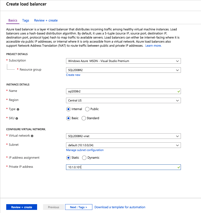
Create a Load Balancer:

Give it a name, select “Internal” as the scheme, make sure your virtual network and subnet are properly selected, and assign a static IP that is the same as the cluster’s Virtual IP address.  In this example it’s 10.0.0.99:


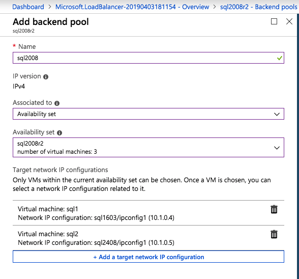
Next, add a backend pool behind the load balancer.  This how you place the two cluster VMs behind this load balancer

Select both of your cluster nodes (node1, node2) and add them to the Backend Pool:


Once saved, expand the backend pool (called “ILBBackEnd” here) and you’ll see both VMs underneath along with their status and IPs.  It may take a few seconds before the screen updates:


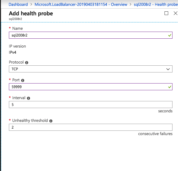
Next, configure a probe for your ILB.  The probe checks the health of a service behind the ILB to determine which node to route traffic to.  Here we will specify port 3306, which is the default for MySQL:


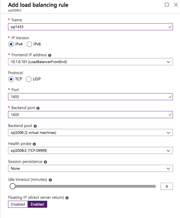
Finally, complete the ILB configuration by creating a Load Balancing Rule.   TCP, Port 3306, and make sure you select “Enabled” for “Floating IP (direct server return)”:


Test Cluster Connectivity

At this point, all of our Azure and Cluster configurations are complete!

Cluster resources are currently active on node1:


SSH into the witness server, “sudo su -” to gain root access.   Install the mysql client if needed:

[root@witness ~]# yum -y install mysql

Test MySQL connectivity to the cluster:

[root@witness ~]# mysql --host=10.0.0.99 mysql -u root -p

Execute the following MySQL query to display the hostname of the active cluster node:

mysql> select @@hostname;
 ------------ 
| @@hostname |
 ------------ 
| node1      |
 ------------ 
1 row in set (0.00 sec)
mysql>

Using LifeKeeper GUI, failover from Node1 -> Node2″.  Right click on the mysql resource underneath node2, and select “In Service…”:


After failover:


After failover has completed, re-run the MySQL query.  You’ll notice that the MySQL client has detected that the session was lost (during failover) and automatically reconnects:

Execute the following MySQL query to display the hostname of the active cluster node, verifying that now “node2” is active:

mysql> select @@hostname;
ERROR 2006 (HY000): MySQL server has gone away
No connection. Trying to reconnect...
Connection id:    48
Current database: mysql
 ------------ 
| @@hostname |
 ------------ 
| node2      |
 ------------ 
1 row in set (0.56 sec)
mysql>

Find these step by step guides to configure Linux Failover Cluster In Microsoft Azure IaaS Without Shared Storage useful? We’ve more here

Reproduced with permission from Linuxclustering

Filed Under: Clustering Simplified Tagged With: Azure, High Availability, linux failover cluster in microsoft azure iaas without shared storage, MySQL

12 Checklist Items for Selecting a High-Availability Solution

December 6, 2018 by Jason Aw Leave a Comment

Selecting a High-Availability Solution

12 Checklist Items For Selecting A High-Availability Solution

When selecting a high-availability solution, you should consider several criteria. These range from the total cost of the solution, to the ease with which you can configure and manage the cluster, to the specific restrictions placed on hardware and software. This post touches briefly on 12 of the most important checklist items.

1. Support For Standard OS And Application Versions

Solutions that require enterprise or advanced versions of the OS, database, or application software can greatly reduce the cost benefits of moving to a commodity server environment. Deploy the proper HA middleware. This way, you can make standard versions of applications and OSs highly available. And at the same time, meet the uptime requirements of your business environment.
2. Support For A Variety Of Data Storage Configurations

When you deploy an HA cluster, the data that the protected applications require must be available to all systems that might need to bring the applications into service. You can share this data via data replication, by using shared SCSI or Fibre Channel storage, or by using a NAS device. Whichever method you decide to deploy, the HA product that you use must be able to support all data configurations so that you can change as your business needs dictate.

3. Ability To Use Heterogeneous Solution Components
Some HA clustering solutions require that every system within the cluster has identical configurations. This requirement is common among hardware-specific solutions in which clustering technology is meant to differentiate servers or storage and among OS vendors that want to limit the configurations they are required to support. This restriction limits your ability to deploy scaled-down servers as temporary backup nodes and to reuse existing hardware in your cluster deployment. Deploying identically configured servers might be the correct choice for your needs, but the decision shouldn’t be dictated by your HA solution provider.
4. Support For More Than Two Nodes Within A Cluster

The number of nodes that can be supported in a cluster is an important measure of scalability. Entry-level HA solutions typically limit you to one two-node cluster, usually in active/passive mode. Although this configuration provides increased availability (via the addition of a standby server), it can still leave you exposed to application downtime. In a two-node cluster configuration, if one server is down for any reason, then the remaining server becomes a single point of failure. By clustering three or more nodes, you gain the ability to provide higher levels of protection. At the same time, you can also build highly scalable configurations.

5. Support For Active/Active And Active/Standby Configurations

Selecting a High-Availability Solution to suit your project is key. In an active/standby configuration, one server is idle, waiting to take over the workload of its cluster member. This setup has the obvious disadvantage of underutilizing your compute resource investment. To get the most benefit from your IT expenditure, ensure that cluster nodes can run in an active/active configuration.

6. Detection Of Problems At Node And Individual Service Levels

All HA software products can detect problems with cluster server functionality. This task is done by sending heartbeat signals between servers within the cluster and initiating a recovery if a cluster member stops delivering the signals. But advanced HA solutions can also detect another class of problems. One that occurs when individual processes or services encounter problems that render them unavailable but that do not cause servers to stop sending or responding to heartbeat signals. Given that the primary function of HA software is to ensure that applications are available to end users, detecting and recovering from these service level interruptions is a crucial feature. Ensure that your HA solution can detect both node- and service-level problems.

7. Support For In-Node And Cross-Node Recovery

The ability to perform recovery actions both across cluster nodes and within a node is also important. In cross-node recovery, one node takes over the complete domain of responsibility for another. When systems-level heartbeats are missed, the server which should have sent the heartbeats is assumed to be out of operation, and other cluster members begin recovery operations. With in-node or local recovery, failed system services first attempt to be restored within the server on which they are running. This task is typically done by stopping and restarting the service and any dependent system resources. This recovery method is much faster and minimizes downtime.

8. Transparency To Client Connections Of Server-Side Recovery

Server-side recovery of an application or even of an entire node should be transparent to client-side users. Through the use of virtualized IP addresses or server names, the mapping of virtual compute resources onto physical cluster entities during recovery, and automatic updating of network routing tables, no changes to client systems are necessary for the systems to access recovered applications and data. Solutions that require manual client-side configuration changes to access recovered applications greatly increase recovery time. They introduce the risk of additional errors due to required human interaction. Recovery should be automated on both the servers and clients.

9. Protection For Planned And Unplanned Downtime

In addition to providing protection against unplanned service outages, the HA solution that you deploy should be usable as an administration tool to lessen downtime caused by maintenance activities. By providing a facility to allow on-demand movement of applications between cluster members, you can migrate applications and users onto a second server while performing maintenance on the first. This can eliminate the need for maintenance windows in which IT resources are unavailable to end users. Ensure that your HA solution provides a simple and secure method for performing manual (on-demand) movement of applications and needed resources among cluster nodes.

10. Off-The-Shelf Protection For Common Business Functions

Every HA solution that you evaluate should include tested and supported agents or modules that are designed to monitor the health of specific system resources: file systems, IP addresses, databases, applications, and so on. These modules are often called recovery modules. By deploying vendor-supplied modules, you benefit from both the run-time that the vendor and other customers have already done. You also have the assurance of ongoing support and maintenance of these solution components.

11. Ability To Easily Incorporate Protection For Custom Business Applications

There will likely be applications, perhaps custom to your corporation, that you want to protect but for which there are no vendor-supplied recovery modules. It is important, therefore, that you have a method for easily incorporating your business application into your HA solution’s protection schema. You should be able to do this without modifying your application, and especially without having to embed any vendor-specific APIs. A software developer’s kit that provides examples and a step-by-step process for protecting your application should be available. Also, along with vendor-supplied support services to assist as needed.

12. Ease Of Cluster Deployment And Management

A common myth surrounding HA clusters is that they are costly and complex to deploy and administer. This is not necessarily true. Cluster administration interfaces should be wizard-driven to assist with initial cluster configuration. It should include auto-discovery of new elements as they are added to the cluster. Similarly, it should allow for at-a-glance status monitoring of the entire cluster. Finally, any cluster metadata must be stored in an HA fashion. Not on a single quorum disk within the cluster, where corruption or an outage could cause the entire cluster to fall apart.
By looking for the capabilities on this checklist, you can make the best decision for your particular HA needs.

Selecting a High-Availability Solution isn’t rocket science. Here are our success stories

Reproduced with permission from Linuxclustering

Filed Under: Clustering Simplified Tagged With: High Availability, selecting a high availability solution

SAP High Availability Solutions For Linux

December 3, 2018 by Jason Aw Leave a Comment

SAP High Availability Solutions

SAP High Availability Solutions For Linux

Are you looking for a powerful yet easy to implement High Availability / Disaster Recovery solution for your SAP environment?  If so, you will want to take a look at the SteelEye Protection Suite (SPS) for Linux, from SIOS Technologies.  SPS provides integrated High Availability and Data Replication functionality that works with any server or storage configuration.  Support for SAP is provided out-of-the-box without the need for any scripting or customizations.

SPS for Linux was recently officially certified by SAP against their “SAP NetWeaver High Availability Cluster 730 Certification” (NW-HA-CLU 730)

A list of certified HA solutions for SAP can be found here:  http://scn.sap.com/docs/DOC-31701

For more information on SAP High Availability Solutions For Linux, do drop us a note
Reproduced with permission from Linuxclustering

Filed Under: Clustering Simplified Tagged With: High Availability, SAP, sap high availability solutions

  • « Previous Page
  • 1
  • …
  • 42
  • 43
  • 44
  • 45
  • 46
  • …
  • 53
  • Next Page »

Recent Posts
  • SIOS Enterprise Support Guide: What Your Plan Covers
  • Why a Sandbox Environment Is Essential for High Availability
  • Inheriting DataKeeper
  • High Availability vs. Fault Tolerance: Key Differences Explained
  • Business Continuity Planning for High Availability and Disaster Recovery

Most Popular Posts

Maximise replication performance for Linux Clustering with Fusion-io
Failover Clustering with VMware High Availability
create A 2-Node MySQL Cluster Without Shared Storage
SAP for High Availability Solutions For Linux
Bandwidth To Support Real-Time Replication
The Availability Equation – High Availability Solutions.jpg
Choosing Platforms To Replicate Data - Host-Based Or Storage-Based?
Guide To Connect To An iSCSI Target Using Open-iSCSI Initiator Software
Best Practices to Eliminate SPoF In Cluster Architecture
Step-By-Step How To Configure A Linux Failover Cluster In Microsoft Azure IaaS Without Shared Storage azure sanless
Take Action Before SQL Server 20082008 R2 Support Expires
How To Cluster MaxDB On Windows In The Cloud

Join Our Mailing List

Copyright © 2026 · Enterprise Pro Theme on Genesis Framework · WordPress · Log in