Step-By-Step: How to configure a SANless MySQL Linux failover cluster in Amazon EC2
In this step by step guide, I will take you through all steps required to configure a highly available, 2-node MySQL cluster (plus witness server) in Amazon’s Elastic Compute Cloud (Amazon EC2). The guide includes both screenshots, shell commands and code snippets as appropriate. I assume that you are somewhat familiar with Amazon EC2 and already have an account. If not, you can sign up today. I’m also going to assume that you have basic familiarity with Linux system administration and failover clustering concepts like Virtual IPs, etc.
Failover clustering has been around for many years. In a typical configuration, two or more nodes are configured with shared storage to ensure that in the event of a failover on the primary node, the secondary or target node(s) will access the most up-to-date data. Using shared storage not only enables a near-zero recovery point objective, it is a mandatory requirement for most clustering software. However, shared storage presents several challenges. First, it is a single point of failure risk. If shared storage – typically a SAN – fails, all nodes in the cluster fails. Second, SANs can be expensive and complex to purchase, setup and manage. Third, shared storage in public clouds, including Amazon EC2 is either not possible, or not practical for companies that want to maintain high availability (99.99% uptime), near-zero recovery time and recovery point objectives, and disaster recovery protection.
The following demonstrates how easy it is to create a SANless cluster in the clouds to eliminate these challenges while meeting stringent HA/DR SLAs. The steps below use MySQL database with Amazon EC2 but the same steps could be adapted to create a 2-node cluster in AWS to protect SQL, SAP, Oracle, or any other application.
NOTE: Your view of features, screens and buttons may vary slightly from screenshots presented below
1. Create a Virtual Private Cloud (VPC)
2. Create an Internet Gateway
3. Create Subnets (Availability Zones)
4. Configure Route Tables
5. Configure Security Group
6. Launch Instances
7. Create Elastic IP
8. Create Route Entry for the Virtual IP
9. Disable Source/Dest Checking for ENIs
10. Obtain Access Key ID and Secret Access Key
11. Linux OS Configuration
12. Install EC2 API Tools
13. Install and Configure MySQL
14. Install and Configure Cluster
15. Test Cluster Connectivity
Overview
This article will describe how to create a cluster within a single Amazon EC2 region. The cluster nodes (node1, node2 and the witness server) will reside different Availability Zones for maximum availability. This also means that the nodes will reside in different subnets.

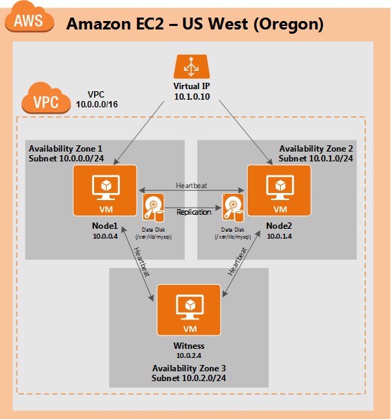
The following IP addresses will be used:
- node1: 10.0.0.4
- node2: 10.0.1.4
- witness: 10.0.2.4
- virtual/”floating” IP: 10.1.0.10
Step 1: Create a Virtual Private Cloud (VPC)
First, create a Virtual Private Cloud (aka VPC). A VPC is an isolated network within the Amazon cloud that is dedicated to you. You have full control over things like IP address blocks and subnets, route tables, security groups (i.e. firewalls), and more. You will be launching your Azure Iaas virtual machines (VMs) into your Virtual Network.
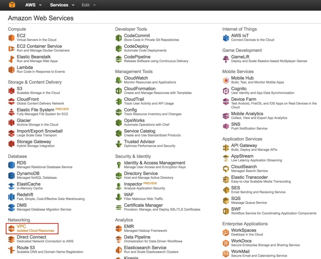
From the main AWS dashboard, select “VPC”
Under “Your VPCs”, make sure you have selected the proper region at the top right of the screen. In this guide the “US West (Oregon)” region will be used, because it is a region that has 3 Availability Zones. For more information on Regions and Availability Zones, click here.
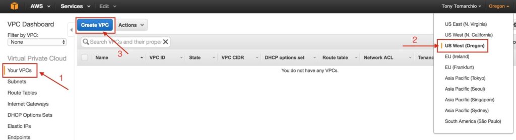
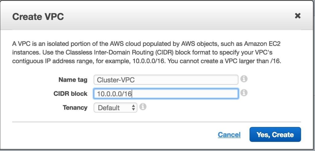
Give the VPC a name, and specify the IP block you wish to use. 10.0.0.0/16 will be used in this guide:
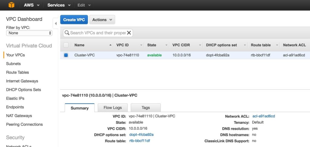
You should now see the newly created VPC on the “Your VPCs” screen:
Step 2: Create an Internet Gateway
Next, create an Internet Gateway. This is required if you want your Instances (VMs) to be able to communicate with the internet.
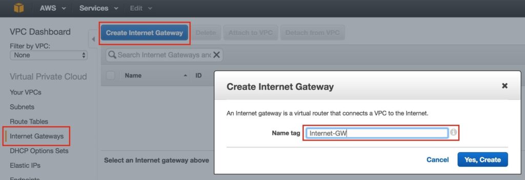
On the left menu, select Internet Gateways and click the Create Internet Gateway button. Give it a name, and create:
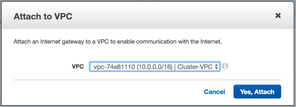
Next, attach the internet gateway to your VPC:
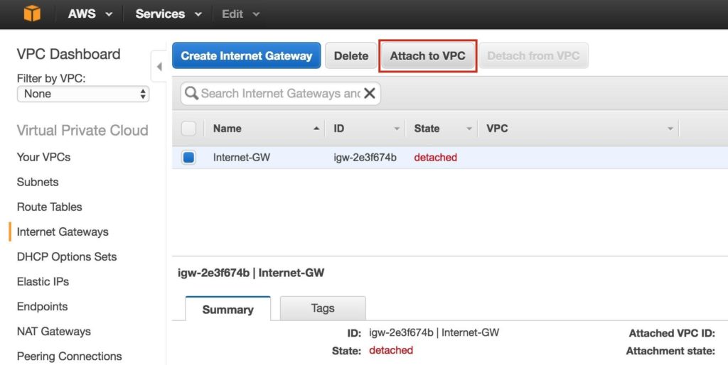
Select your VPC, and click Attach:
Step 3: Create Subnets (Availability Zones)
Next, create 3 subnets. Each subnet will reside in it’s own Availability Zone. The 3 Instances (VMs: node1, node2, witness) will be launched into separate subnets (and therefore Availability Zones) so that the failure of an Availability Zone won’t take out multiple nodes of the cluster.
The US West (Oregon) region, aka us-west-2, has 3 availability zones (us-west-2a, us-west-2b, us-west-2c). Create 3 subnets, one in each of the 3 availability zones.
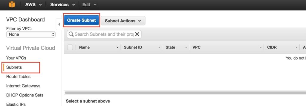
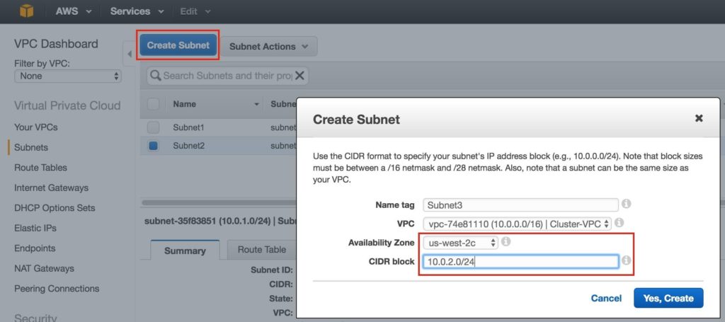
Under VPC Dashboard, navigate to Subnets, and then Create Subnet:
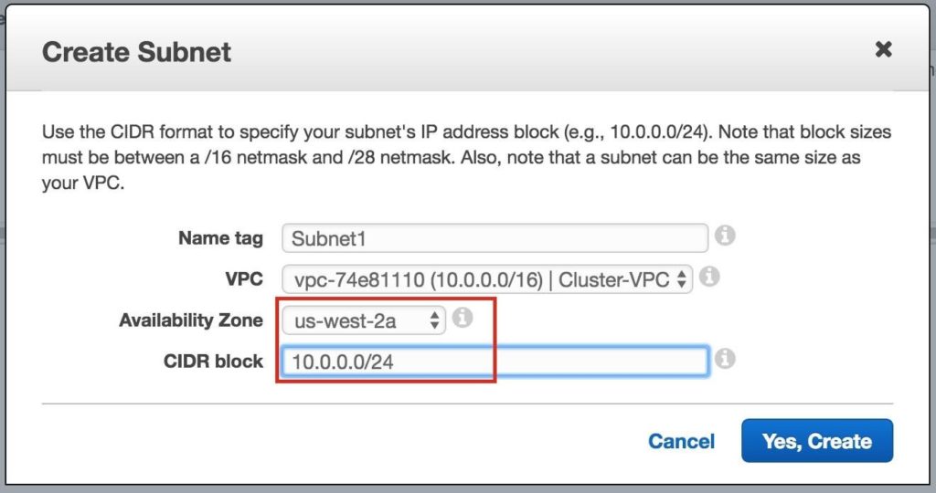
Give the first subnet a name (“Subnet1)”, select the availability zone us-west-2a, and define the network block (10.0.0.0/24):
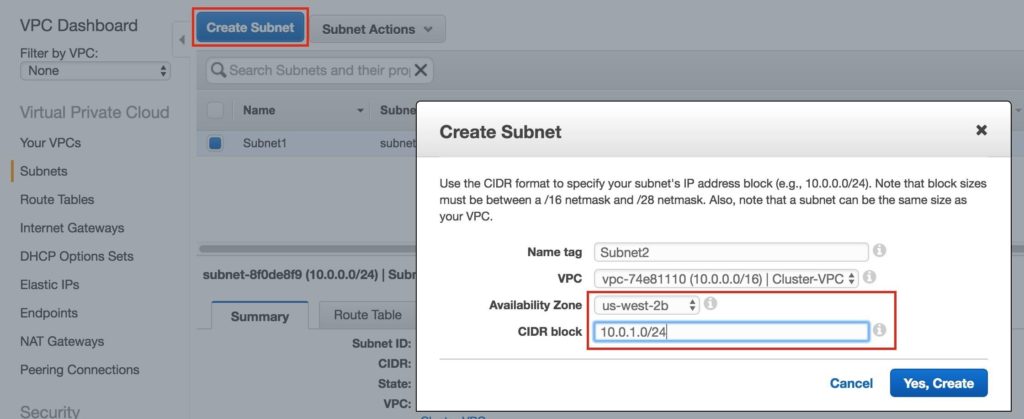
Repeat to create the second subnet availability zone us-west-2b:
Repeat to create the third subnet in availability zone us-west-2c:
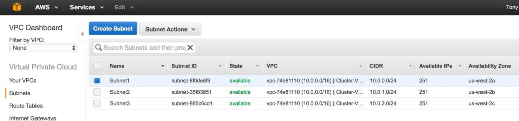
Once complete, verify that the 3 subnets have been created, each with a different CIDR block, and in separate Availability Zones, as seen below:
Step 4: Configure Route Tables
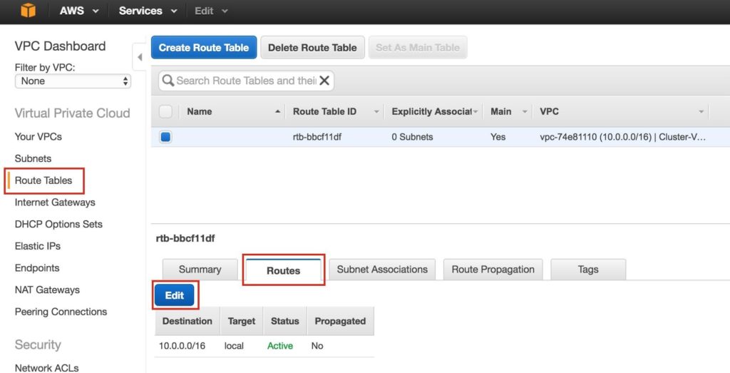
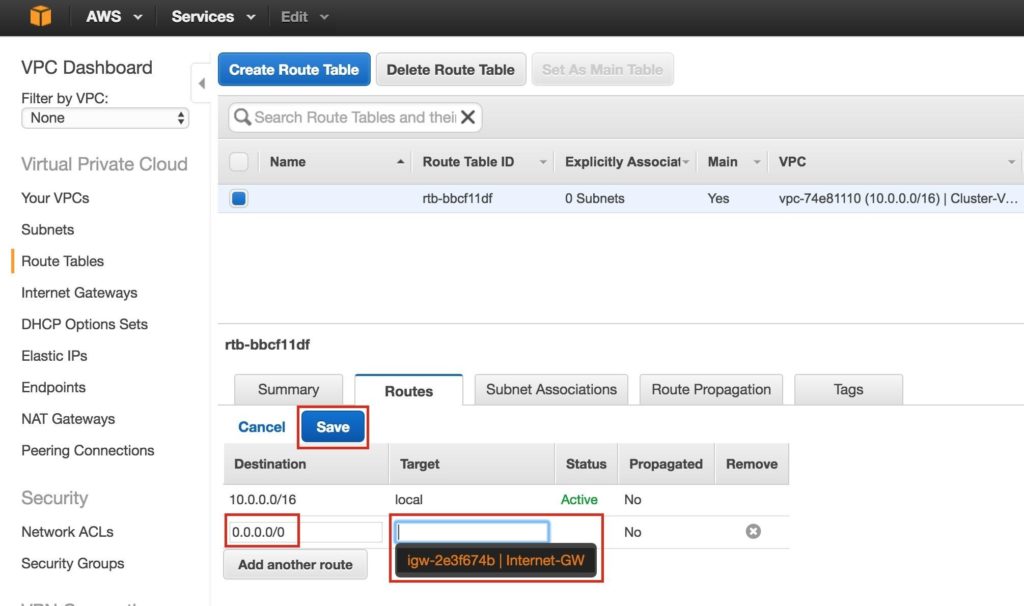
Update the VPC’s route table so that traffic to the outside world is sent to the Internet Gateway created in a previous step. From the VPC Dashboard, select Route Tables. Go to the Routes tab, and by default only one route will exist which allows traffic only within the VPC.
Click Edit:
Add another route:
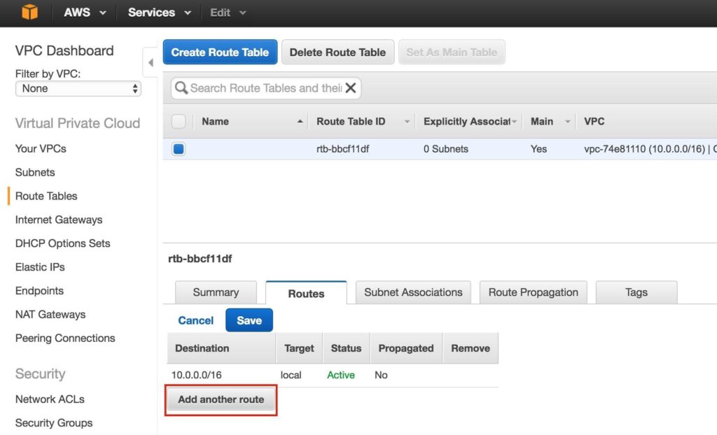
The Destination of the new route will be “0.0.0.0/0” (the internet) and for Target, select your Internet Gateway. Then click Save:
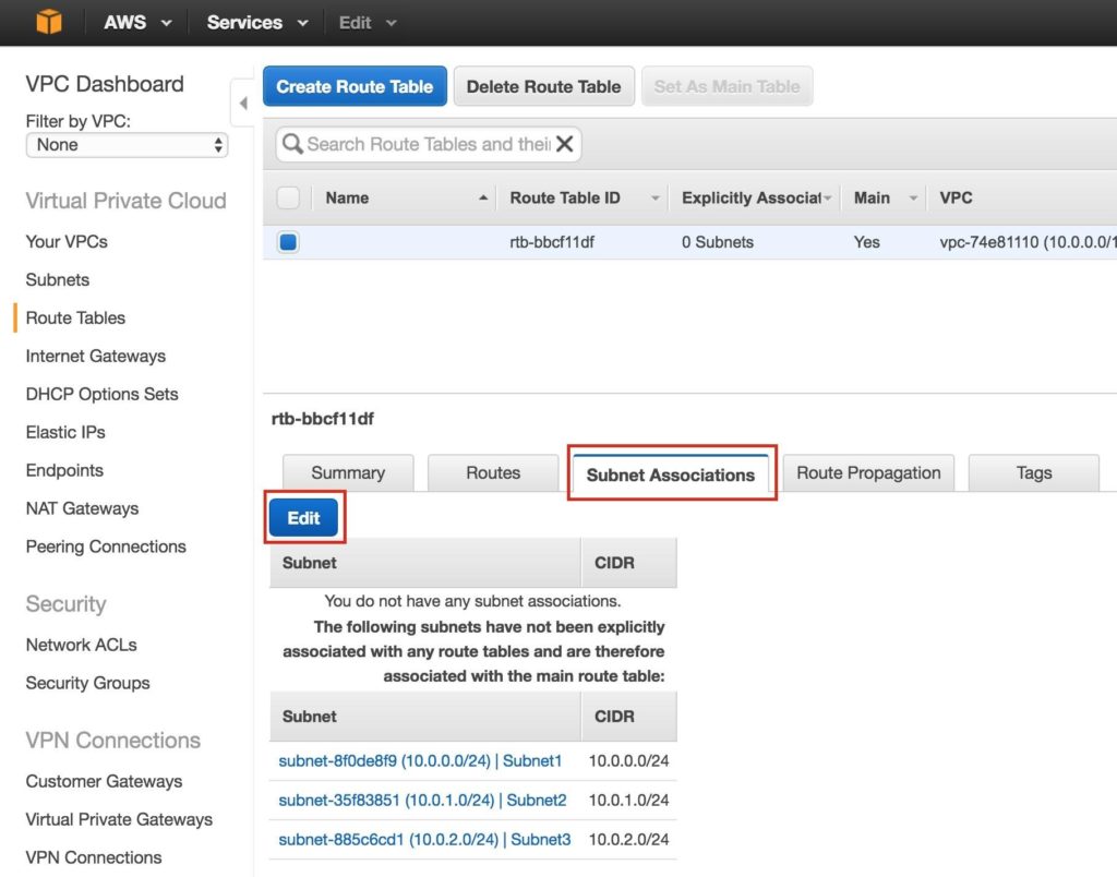
Next, associate the 3 subnets with the Route Table. Click the “Subnet Associations” tab, and Edit:
Check the boxes next to all 3 subnets, and Save:
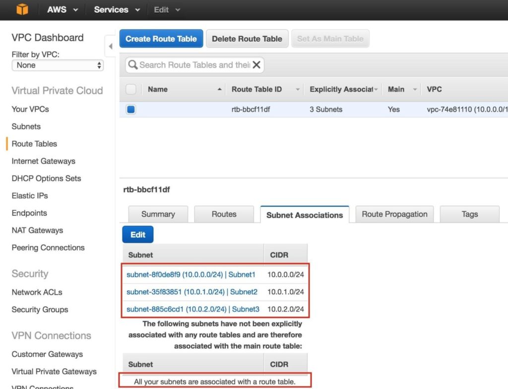
Verify that the 3 subnets are associated with the main route table:

Later, we will come back and update the Route Table once more, defining a route that will allow traffic to communicate with the cluster’s Virtual IP, but this needs to be done AFTER the linux Instances (VMs) have been created.
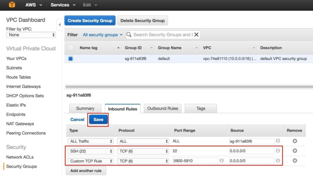
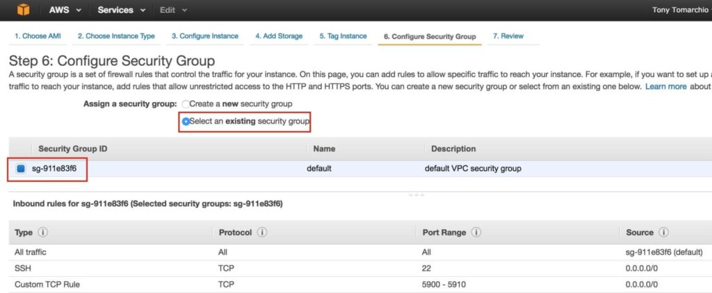
Step 5: Configure Security Group
Edit the Security Group (a virtual firewall) to allow incoming SSH and VNC traffic. Both will later be used to configure the linux instances as well as installation/configuration of the cluster software.
On the left menu, select “Security Groups” and then click the “Inbound Rules” tab. Click Edit:
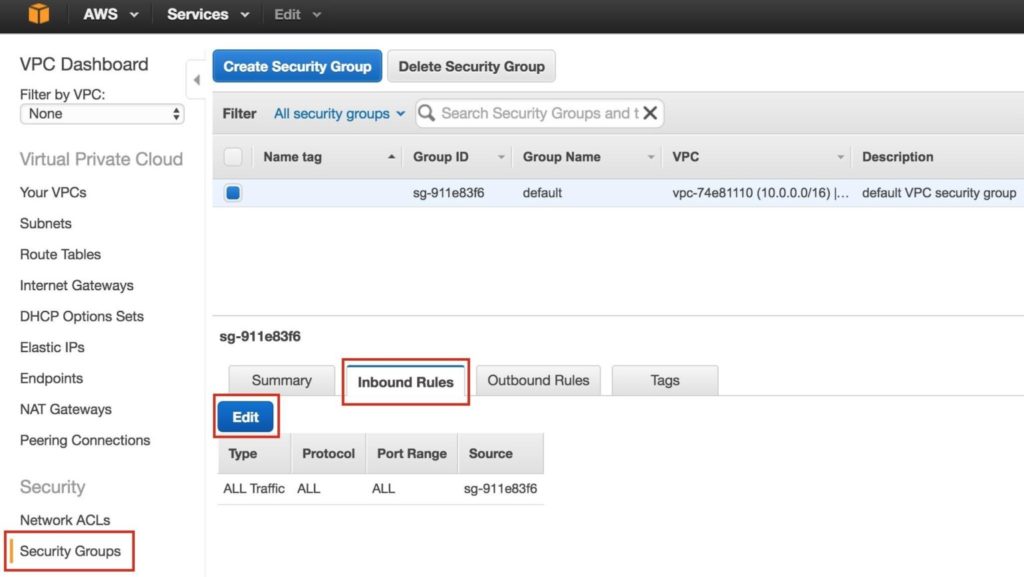
Add rules for both SSH (port 22) and VNC. VNC generally uses ports in the 5900, depending on how you configure it, so for the purposes of this guide, we will open the 5900-5910 port range. Configure accordingly based on your VNC setup:
Step 6: Launch Instances
We will be provisioning 3 Instances (Virtual Machines) in this guide. The first two VMs (called “node1” and “node2”) will function as cluster nodes with the ability to bring the MySQL database and it’s associated resources online. The 3rd VM will act as the cluster’s witness server for added protection against split-brain.
To ensure maximum availability, all 3 VMs will be deployed into different Availability Zones within a single region. This means each instance will reside in a different subnet.
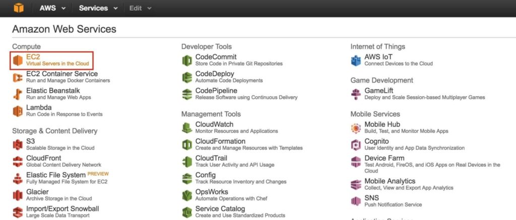
Go to the main AWS dashboard, and select EC2:
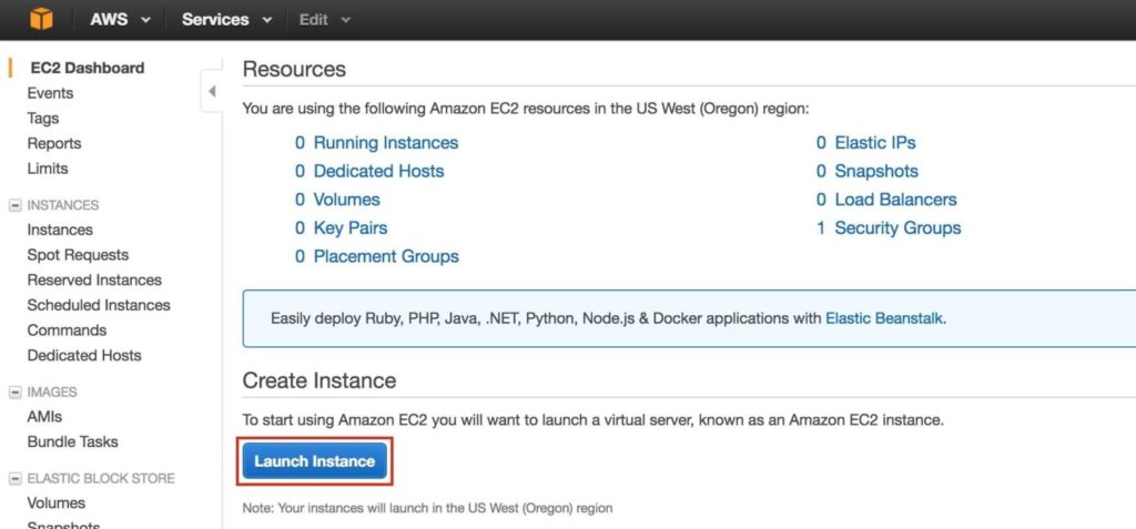
Create “node1”
Create your first instance (“node1”). Click Launch Instance:
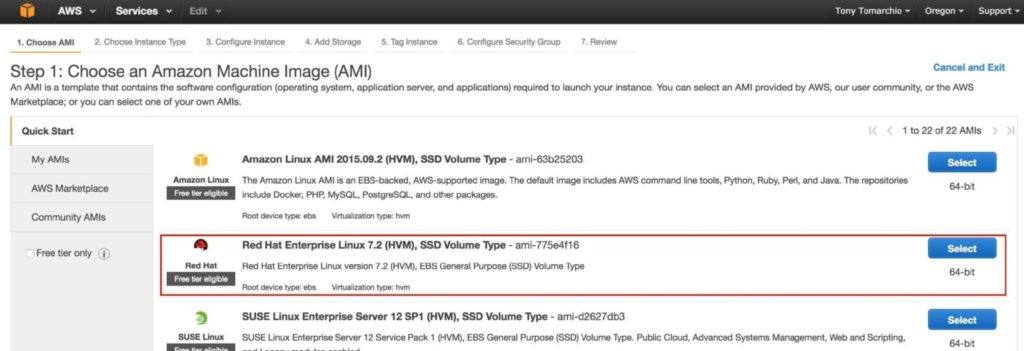
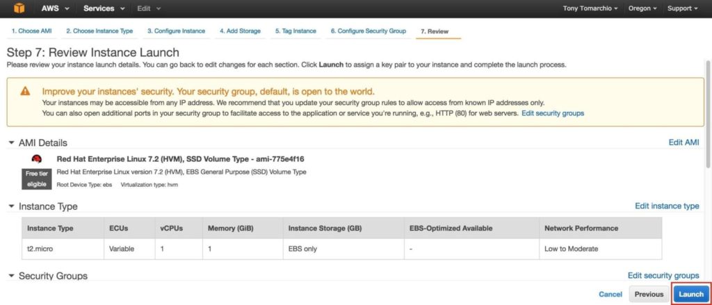
Select your linux distribution. The cluster software used later supports RHEL, SLES, CentOS and Oracle Linux. In this guide we will be using RHEL 7.X:
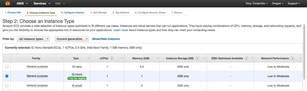
Size your instance accordingly. For the purposes of this guide and to minimize cost, t2.micro size was used because it’s free tier eligible. See here for more information on instance sizes and pricing.
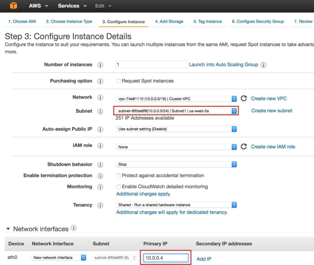
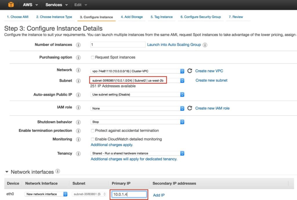
Next, configure instance details. IMPORTANT: make sure to launch this first instance (VM) into “Subnet1“, and define an IP address valid for the subnet (10.0.0.0/24) – below 10.0.0.4 is selected because it’s the first free IP in the subnet.
NOTE: .1/.2/.3 in any given subnet in AWS is reserved and can’t be used.
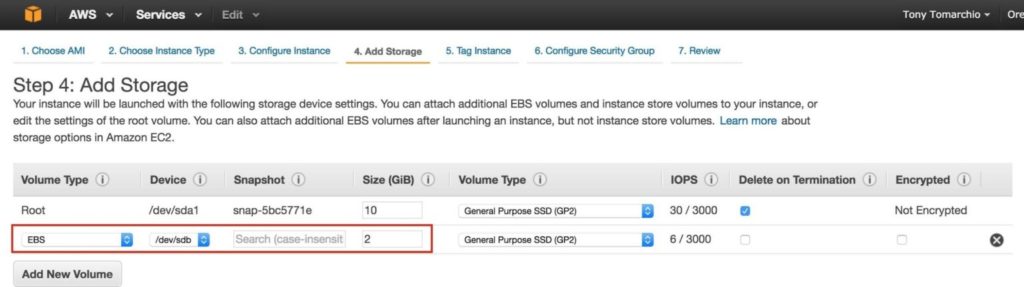
Next, add an extra disk to the cluster nodes (this will be done on both “node1” and “node2”). This disk will store our MySQL databases and the later be replicated between nodes.
NOTE: You do NOT need to add an extra disk to the “witness” node. Only “node1” and “node2”. Add New Volume, and enter in the desired size:
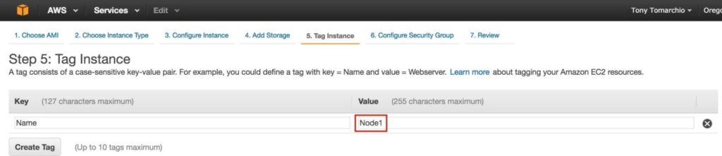
Define a Tag for the instance, Node1:
Associate the instance with the existing security group, so the firewall rules created previous will be active:
Click Launch:
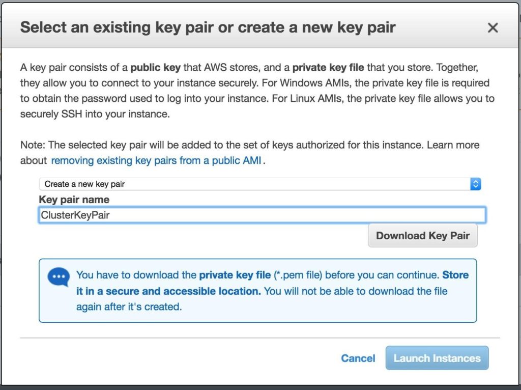
IMPORTANT: If this is the first instance in your AWS environment, you’ll need to create a new key pair. The private key file will need to be stored in a safe location as it will be required when you SSH into the linux instances.
Create “node2”
Repeat the steps above to create your second linux instance (node2). Configure it exactly like Node1. However, make sure that you deploy it into “Subnet2” (us-west-2b availability zone). The IP range for Subnet2 is 10.0.1.0/24, so an IP of 10.0.1.4 is used here:
Make sure to add a 2nd disk to Node2 as well. It should be the same exact size as the disk you added to Node1:

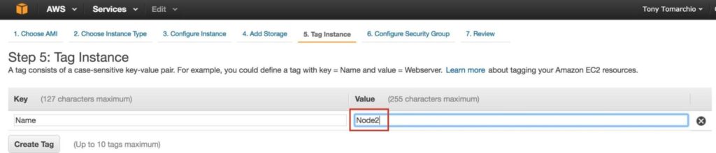
Give the second instance a tag…. “Node2”:
Create “witness”
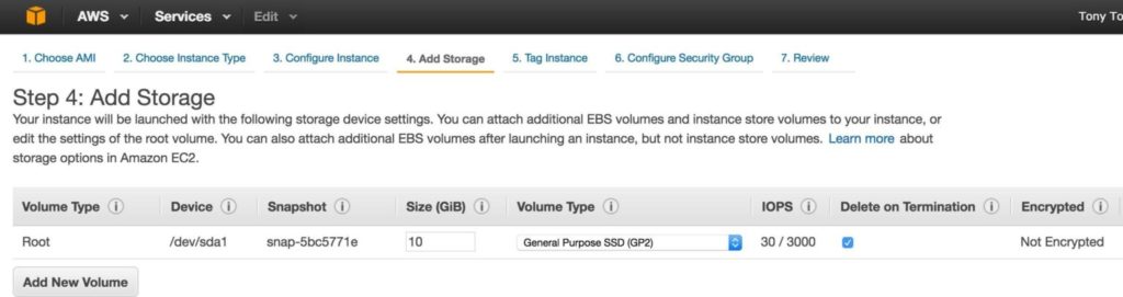
Repeat the steps above to create your third linux instance (witness). Configure it exactly like Node1&Node2, EXCEPT you DON’T need to add a 2nd disk, since this instance will only act as a witness to the cluster, and won’t ever bring MySQL online.
Make sure that you deploy it into “Subnet3” (us-west-2c availability zone). The IP range for Subnet2 is 10.0.2.0/24, so an IP of 10.0.2.4 is used here:
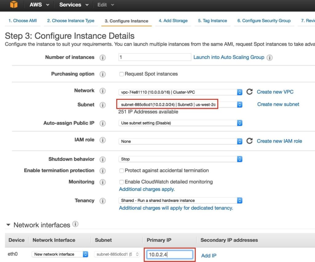
NOTE: default disk configuration is fine for the witness node. A 2nd disk is NOT required:
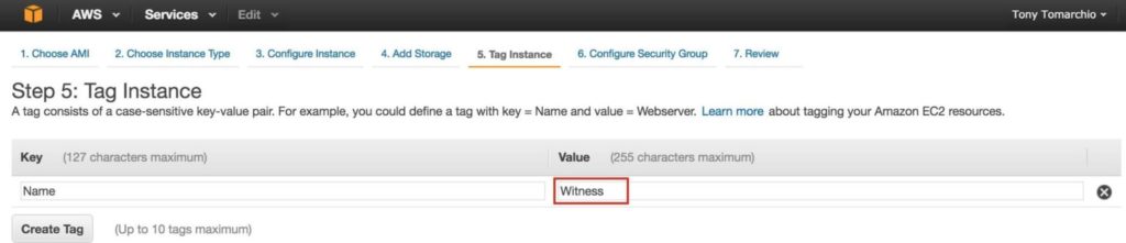
Tag the witness node:
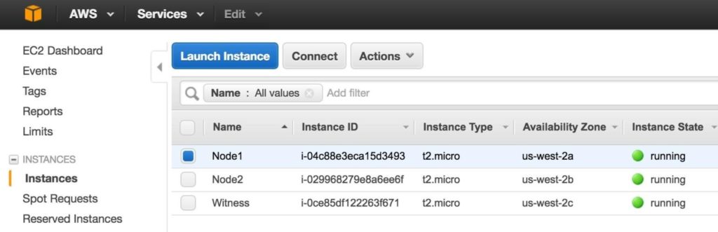
It may take a little while for your 3 instances to provision. Once complete, you’ll see then listed as running in your EC2 console:
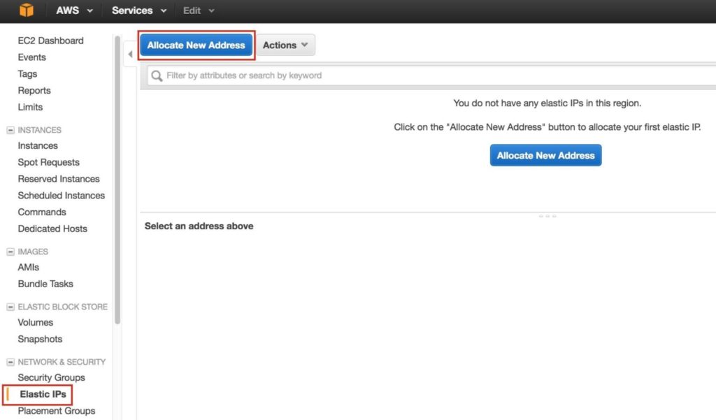
Step 7: Create Elastic IP
Next, create an Elastic IP, which is a public IP address that will be used to connect into you instance from the outside world. Select Elastic IPs in the left menu, and then click “Allocate New Address”:
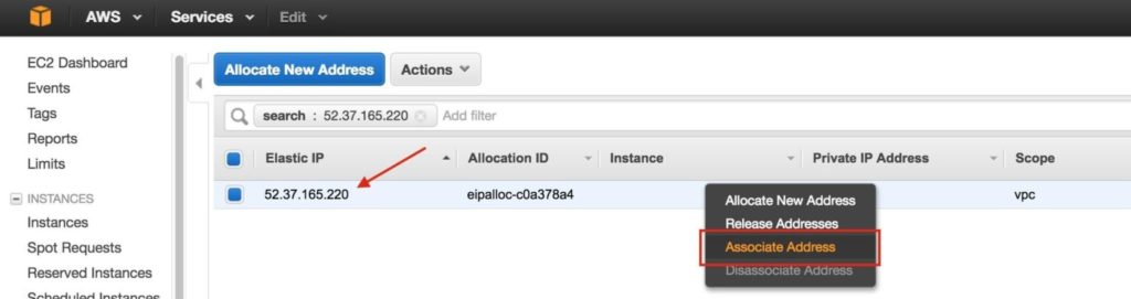
Select the newly created Elastic IP, right-click, and select “Associate Address”:
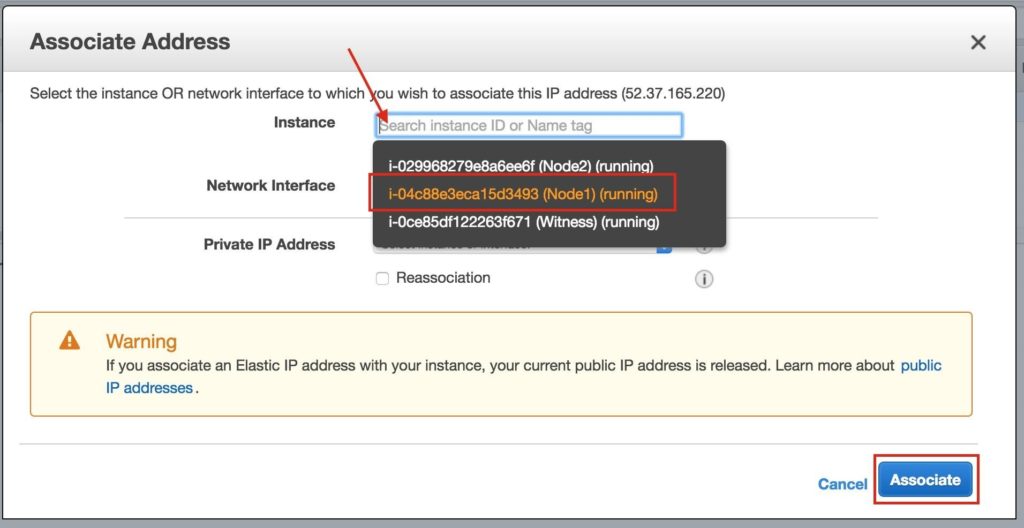
Associate this Elastic IP with Node1:
Repeat this for the other two instances if you want them to have internet access or be able to SSH/VNC into them directly.
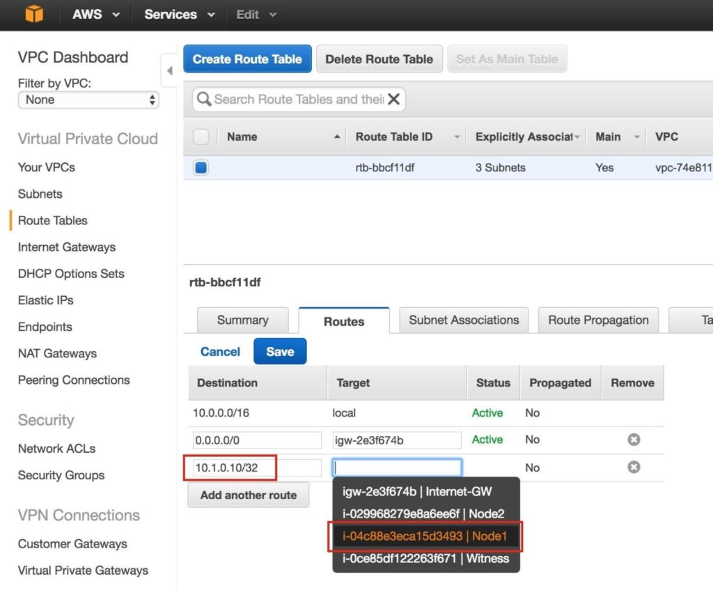
Step 8: create Route Entry for the Virtual IP
At this point all 3 instances have been created, and the route table will need to be updated one more time in order for the cluster’s Virtual IP to work. In this multi-subnet cluster configuration, the Virtual IP needs to live outside the range of the CIDR allocated to your VPC.
Define a new route that will direct traffic to the cluster’s Virtual IP (10.1.0.10) to the primary cluster node (Node1)
From the VPC Dashboard, select Route Tables, click Edit. Add a route for “10.1.0.10/32” with a destination of Node1:
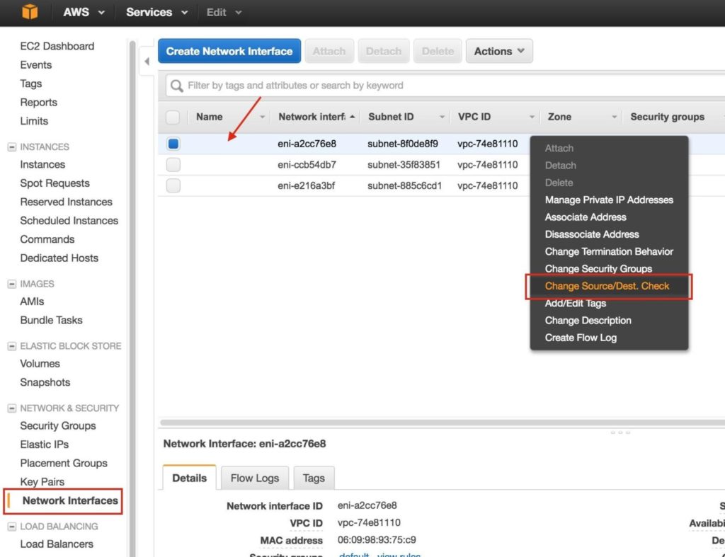
Step 9: Disable Source/Dest Checking for ENIs
Next, disable Source/Dest Checking for the Elastic Network Interfaces (ENI) of your cluster nodes. This is required in order for the instances to accept network packets for the virtual IP address of the cluster.
Do this for all ENIs.
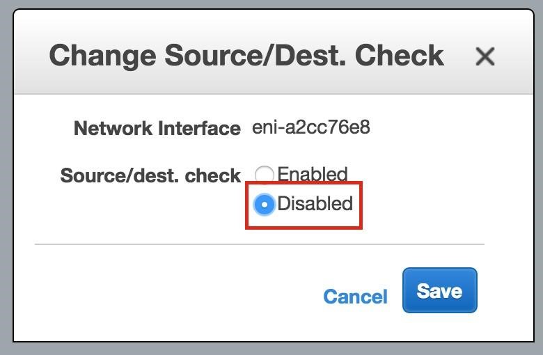
Select “Network Interfaces”, right-click on an ENI, and select “Change Source/Dest Check”.
Select “Disabled“:
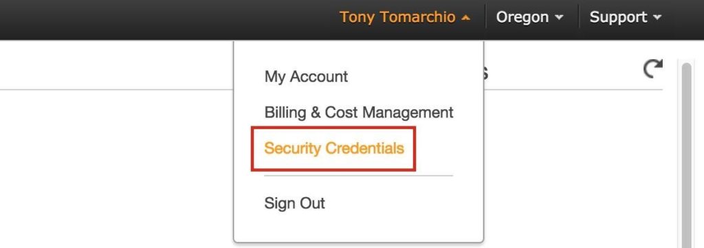
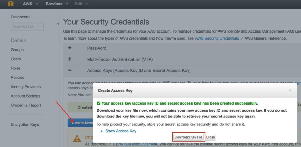
Step 10: Obtain Access Key ID and Secret Access Key
Later in the guide, the cluster software will use the AWS Command Line Interface (CLI) to manipulate a route table entry for the cluster’s Virtual IP to redirect traffic to the active cluster node. In order for this to work, you will need to obtain an Access Key ID and Secret Access Key so that the AWS CLI can authenticate properly.
In the top-right of the EC2 Dashboard, click on your name, and underneath select “Security Credentials” from the drop-down:
Expand the “Access Keys (Access Key ID and Secret Access Key)” section of the table, and click “Create New Access Key”. Download Key File and store the file in a safe location.
Step 11: Configure Linux OS
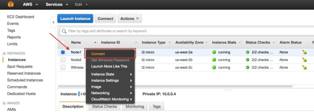
Connect to the linux instance(s):
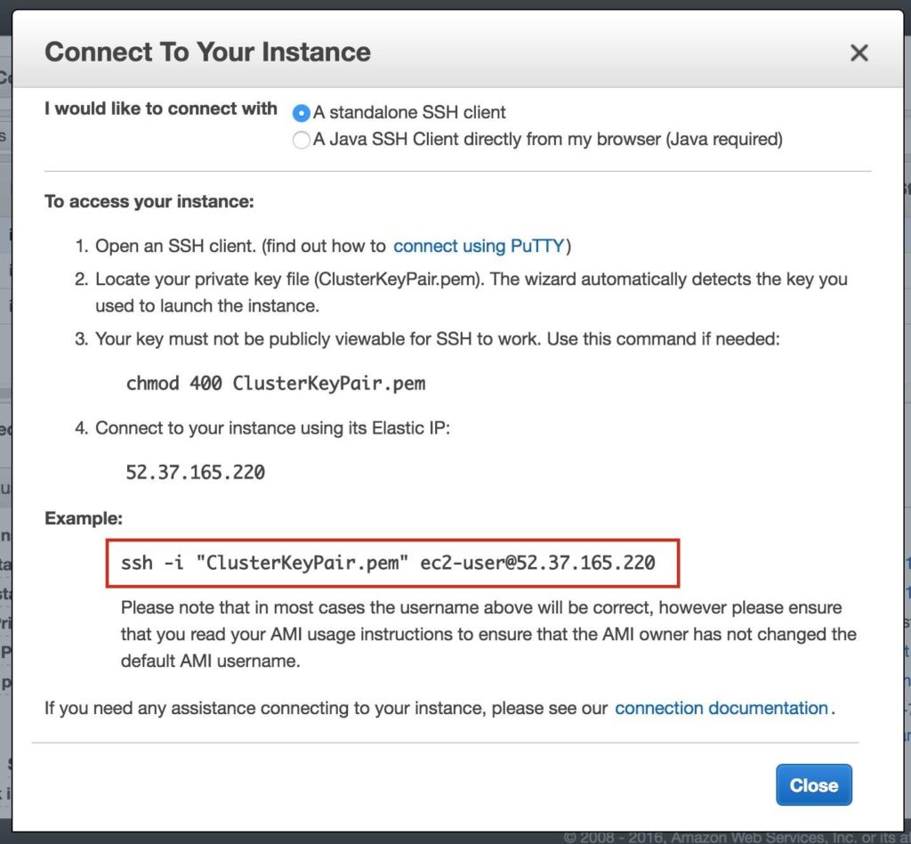
To connect to your newly created linux instances (via SSH), right-click on the instance and select “Connect”. This will display the instructions for connecting to the instance. You will need the Private Key File you created/downloaded in a previous step:
Example:
Here is where we will leave the EC2 Dashboard for a little while and get our hands dirty on the command line, which as a Linux administrator you should be used to by now.
You aren’t given the root password to your Linux VMs in AWS (or the default “ec2-user” account either), so once you connect, use the “sudo” command to gain root privileges:
$sudo su –
Unless you have already have a DNS server setup, you’ll want to create host file entries on all 3 servers so that they can properly resolve each other by nameEdit /etc/hosts
Add the following lines to the end of your /etc/hosts file:
10.0.0.4 node1
10.0.1.4 node2
10.0.2.4 witness
10.1.0.10 mysql-vip
Disable SELinux
Edit /etc/sysconfig/linux and set “SELINUX=disabled”:
# vi /etc/sysconfig/selinux
# This file controls the state of SELinux on the system. # SELINUX= can take one of these three values:
# enforcing – SELinux security policy is enforced.
# permissive – SELinux prints warnings instead of enforcing.
# disabled – No SELinux policy is loaded.
SELINUX=disabled
# SELINUXTYPE= can take one of these two values:
# targeted – Targeted processes are protected, # mls – Multi Level Security protection.
SELINUXTYPE=targeted
Set Hostnames
By default, these Linux instances will have a hostname that is based upon the server’s IP address, something like “ip-10-0-0-4.us-west-2.compute.internal”
You might notice that if you attempt to modify the hostname the “normal” way (i.e. editing /etc/sysconfig/network, etc), after each reboot, it reverts back to the original!! I found a great thread in the AWS discussion forums that describes how to actually get hostnames to remain static after reboots.
Details here: https://forums.aws.amazon.com/message.jspa?messageID=560446
Comment out modules that set hostname in “/etc/cloud/cloud.cfg” file. The following modules can be commented out using #.
# – set_hostname
# – update_hostname
Next, also change your hostname in /etc/hostname.
Reboot Cluster Nodes
Reboot all 3 instances so that SELinux is disabled, and the hostname changes take effect.
Install and Configure VNC (and related packages)
In order to access the GUI of our linux servers, and to later install and configure our cluster, install VNC server, as well as a handful of other required packages (cluster software needs the redhat-lsb and patch rpms).
# yum groupinstall “X Window System”
# yum groupinstall “Server with GUI”
# yum install tigervnc-server xterm wget unzip patch redhat-lsb
# vncpasswd
The following URL is a great guide to getting VNC Server running on RHEL 7 / CentOS 7:For RHEL 7.x/CentOS7.x:
NOTE: This example configuration runs VNC on display 2 (:2, aka port 5902) and as root (not secure). Adjust accordingly!
# cp /lib/systemd/system/vncserver@.service /etc/systemd/system/vncserver@:2.serv
# vi /etc/systemd/system/vncserver@:2.service
[Service]
Type=forking
# Clean any existing files in /tmp/.X11-unix environment ExecStartPre=/bin/sh -c ‘/usr/bin/vncserver -kill %i > /dev/null 2>&1 || :’
ExecStart=/sbin/runuser -l root -c “/usr/bin/vncserver %i -geometry 1024×768” PIDFile=/root/.vnc/%H%i.pid
ExecStop=/bin/sh -c ‘/usr/bin/vncserver -kill %i > /dev/null 2>&1 || :’
# systemctl daemon-reload
# systemctl enable vncserver@:2.service
# vncserver :2 -geometry 1024×768
For RHEL/CentOS 6.x systems:
# vi /etc/sysconfig/vncservers
VNCSERVERS=”2:root” VNCSERVERARGS[2]=”-geometry 1024×768″
# service vncserver start
# chkconfig vncserver on
Open a VNC client, and connect to the <ElasticIP:2>. If you can’t get it, it’s likely your linux firewall is in the way. Either open the VNC port we are using here (port 5902), or for now, disable the firewall (NOT RECOMMENDED FOR PRODUCTION ENVIRONMENTS):
# systemctl stop firewalld
# systemctl disable firewalld
Partition and Format the “data” disk
When the linux instances were launched, and extra disk was added to each cluster node to store the application data we will be protecting. In this case it happens to be MySQL databases.
The second disk should appear as /dev/xvdb. You can run the “fdisk -l” command to verify. You’ll see that
/dev/xvda (OS) is already being used.
# fdisk -l
# Start End Size Type NameDisk /dev/xvda: 10.7 GB, 10737418240 bytes, 20971520 sectors Units = sectors of 1 * 512 = 512 bytes
Sector size (logical/physical): 512 bytes / 512 bytes I/O size (minimum/optimal): 512 bytes / 512 bytes Disk label type: gpt
1 2048 4095 1M BIOS boot parti
2 4096 20971486 10G Microsoft basic
Disk /dev/xvdb: 2147 MB, 2147483648 bytes, 4194304 sectors Units = sectors of 1 * 512 = 512 bytes
Sector size (logical/physical): 512 bytes / 512 bytes I/O size (minimum/optimal): 512 bytes / 512 bytes
Here I will create a partition (/dev/xvdb1), format it, and mount it at the default location for MySQL, which is
/var/lib/mysql. Perform the following steps on BOTH “node1” and “node2”:
# fdisk /dev/xvdb
Welcome to fdisk (util-linux 2.23.2).
Changes will remain in memory only, until you decide to write them. Be careful before using the write command.
Device does not contain a recognized partition table
Building a new DOS disklabel with disk identifier 0x8c16903a.
Command (m for help): n
Partition type:
p primary (0 primary, 0 extended, 4 free) e extended
Select (default p): p
Partition number (1-4, default 1): 1
First sector (2048-4194303, default 2048): <enter>
Using default value 2048
Last sector, +sectors or +size{K,M,G} (2048-4194303, default 4194303): <enter>
Using default value 4194303
Partition 1 of type Linux and of size 2 GiB is set
Command (m for help): w
The partition table has been altered!
Calling ioctl() to re-read partition table. Syncing disks.
# mkfs.ext4 /dev/xvdb1
# mkdir /var/lib/mysql
On node1, mount the filesystem:
# mount /dev/xvdb1 /var/lib/mysql
The EC2 API Tools (EC2 CLI) must be installed on each of the cluster nodes, so that the cluster software can later manipulate Route Tables, enabling connectivity to the Virtual IP.
Step 12: Install EC2 API Tools
The following URL is an excellent guide to setting this up:
http://docs.aws.amazon.com/AWSEC2/latest/CommandLineReference/set-up-ec2-cli-linux.html
Here are the key steps:
Download, unzip, and move the CLI tools to the standard location (/opt/aws):
# wget http://s3.amazonaws.com/ec2-downloads/ec2-api-tools.zip
# unzip ec2-api-tools.zip
# mv ec2-api-tools-1.7.5.1/ /opt/aws/
# export EC2_HOME=”/opt/aws”
If java isn’t already installed (run “which java” to check), install it:
# yum install java-1.8.0-openjdk
# export JAVA_HOME=”/usr/lib/jvm/java-1.8.0-openjdk-1.8.0.71-
Example (Based on default config of RHEL 7.2 system. Adjust accordingly)
You’ll need your AWS Access Key and AWS Secret Key. Keep these values handy, because they will be needed later during cluster setup too! Refer to the following URL for more information:
https://console.aws.amazon.com/iam/home?#security_credential
# export AWS_ACCESS_KEY=your-aws-access-key-id
# export AWS_SECRET_KEY=your-aws-secret-key
Test CLI utility functionality:
# /opt/aws/bin/ec2-describe-regions
REGION eu-west-1 ec2.eu-west-1.amazonaws.com
REGION ap-southeast-1 ec2.ap-southeast-1.amazonaws.com
REGION ap-southeast-2 ec2.ap-southeast-2.amazonaws.com
REGION eu-central-1 ec2.eu-central-1.amazonaws.com
REGION ap-northeast-2 ec2.ap-northeast-2.amazonaws.com
REGION ap-northeast-1 ec2.ap-northeast-1.amazonaws.com
REGION us-east-1 ec2.us-east-1.amazonaws.com
REGION sa-east-1 ec2.sa-east-1.amazonaws.com
REGION us-west-1 ec2.us-west-1.amazonaws.com
REGION us-west-2 ec2.us-west-2.amazonaws.com
Step 13: Install and Configure MySQL
Next, install the MySQL packages, initialize a sample database, and set “root” password for MySQL. In RHEL7.X, the MySQL packages have been replaced with the MariaDB packages.
On “node1”:
# yum install mariadb mariadb-server
# mount /dev/xvdb1 /var/lib/mysql
# /usr/bin/mysql_install_db –datadir=”/var/lib/mysql/” –user=mysql
# mysqld_safe –user=root –socket=/var/lib/mysql/mysql.sock –port=3306 –datadi
#
# # NOTE: This next command allows remote connections from ANY host. NOT a good # echo “update user set Host=’%’ where Host=’node1′; flush privileges | mysql mys #
# #Set MySQL’s root password to ‘SIOS’
# echo “update user set Password=PASSWORD(‘SIOS’) where User=’root’; flush
Create a MySQL configuration file. We will place this on the data disk (that will later be replicated –
/var/lib/mysql/my.cnf). Example:
# vi /var/lib/mysql/my.cnf
[mysqld] datadir=/var/lib/mysql
socket=/var/lib/mysql/mysql.sock
pid-file=/var/run/mariadb/mariadb.pid user=root
port=3306
# Disabling symbolic-links is recommended to prevent assorted security risks symbolic-links=0
[mysqld_safe]
log-error=/var/log/mariadb/mariadb.log pid-file=/var/run/mariadb/mariadb.pid
[client] user=root password=SIOS
Move the original MySQL configuration file aside, if it exists:
# mv /etc/my.cnf /etc/my.cnf.orig
On “node2”, you ONLY need to install the MariaDB/MySQL packages. The other steps aren’t required:On “node2”:
[root@node2 ~]# yum install mariadb mariadb-server
Step 14: Install and Configure the Cluster
At this point, we are ready to install and configure our cluster. SIOS Protection Suite for Linux (aka SPS-Linux) will be used in this guide as the clustering technology. It provides both high availability failover clustering features (LifeKeeper) as well as real-time, block level data replication (DataKeeper) in a single, integrated solution. SPS-Linux enables you to deploy a “SANLess” cluster, aka a “shared nothing” cluster meaning that cluster nodes don’t have any shared storage, as is the case with EC2 Instances.
Install SIOS Protection Suite for Linux
Perform the following steps on ALL 3 VMs (node1, node2, witness):
Download the SPS-Linux installation image file (sps.img) and and obtain either a trial license or purchase permanent licenses. Contact SIOS for more information.
You will loopback mount it and run the “setup” script inside, as root (or first “sudo su -” to obtain a root shell) For example:
# mkdir /tmp/install
# mount -o loop sps.img /tmp/install
# cd /tmp/install
# ./setup
During the installation script, you’ll be prompted to answer a number of questions. You will hit Enter on almost every screen to accept the default values. Note the following exceptions:
- On the screen titled “High Availability NFS” you may select “n” as we will not be creating a highly available NFS server
- Towards the end of the setup script, you can choose to install a trial license key now, or later. We will install the license key later, so you can safely select “n” at this point
- In the final screen of the “setup” select the ARKs (Application Recovery Kits, i.e. “cluster agents”) you wish to install from the list displayed on the screen.
- The ARKs are ONLY required on “node1” and “node2”. You do not need to install on “witness” Navigate the list with the up/down arrows, and press SPACEBAR to select the following:
-
- lkDR – DataKeeper for Linux
- lkSQL – LifeKeeper MySQL RDBMS Recovery Kit
- This will result in the following additional RPMs installed on “node1” and “node2”:
- steeleye-lkDR-9.0.2-6513.noarch.rpm steeleye-lkSQL-9.0.2-6513.noarch.rpm
-
- The ARKs are ONLY required on “node1” and “node2”. You do not need to install on “witness” Navigate the list with the up/down arrows, and press SPACEBAR to select the following:
Install Witness/Quorum package
The Quorum/Witness Server Support Package for LifeKeeper (steeleye-lkQWK) combined with the existing failover process of the LifeKeeper core allows system failover to occur with a greater degree of confidence in situations where total network failure could be common. This effectively means that failovers can be done while greatly reducing the risk of “split-brain” situations.
Install the Witness/Quorum rpm on all 3 nodes (node1, node2, witness):
# cd /tmp/install/quorum
# rpm -Uvh steeleye-lkQWK-9.0.2-6513.noarch.rpm
On ALL 3 nodes (node1, node2, witness), edit /etc/default/LifeKeeper, set NOBCASTPING=1
On ONLY the Witness server (“witness”), edit /etc/default/LifeKeeper, set WITNESS_MODE=off/none
Install the EC2 Recovery Kit Package
SPS-Linux provides specific features that allow resources to failover between nodes in different availability zones and regions. Here, the EC2 Recovery Kit (i.e. cluster agent) is used to manipulate Route Tables so that connections to the Virtual IP are routed to the active cluster node.
Install the EC2 rpm (node1, node2):
# cd /tmp/install/amazon
# rpm -Uvh steeleye-lkECC-9.0.2-6513.noarch.rpm
Install a License key
On all 3 nodes, use the “lkkeyins” command to install the license file that you obtained from SIOS:
# /opt/LifeKeeper/bin/lkkeyins <path_to_file>/<filename>.lic
Start LifeKeeper
On all 3 nodes, use the “lkstart” command to start the cluster software:
# /opt/LifeKeeper/bin/lkstart
Set User Permissions for LifeKeeper GUI
On all 3 nodes, create a new linux user account (i.e. “tony” in this example). Edit /etc/group and add the “tony” user to the “lkadmin” group to grant access to the LifeKeeper GUI. By default only “root” is a member of the group, and we don’t have the root password here:
# useradd tony
# passwd tony
# vi /etc/group
lkadmin:x:1001:root,tony
Open the LifeKeeper GUI
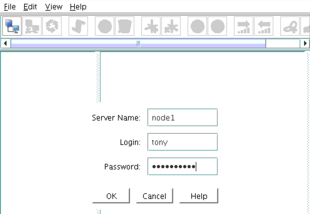
Make a VNC connection to the Elastic IP (Public IP) address of node1. Based on the VNC configuration from above, you would connect to <Public_IP>:2 using the VNC password you specified earlier. Once logged in, open a terminal window and run the LifeKeeper GUI using the following command:
# /opt/LifeKeeper/bin/lkGUIapp &
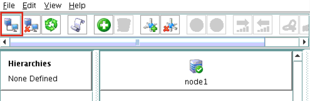
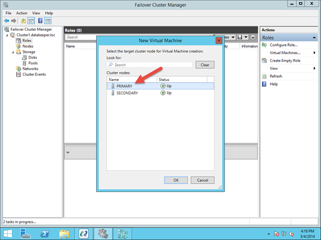
You will be prompted to connect to your first cluster node (“node1”). Enter the linux userid and password specified during VM creation:
Next, connect to both “node2” and “witness” by clicking the “Connect to Server” button highlighted in the following screenshot:
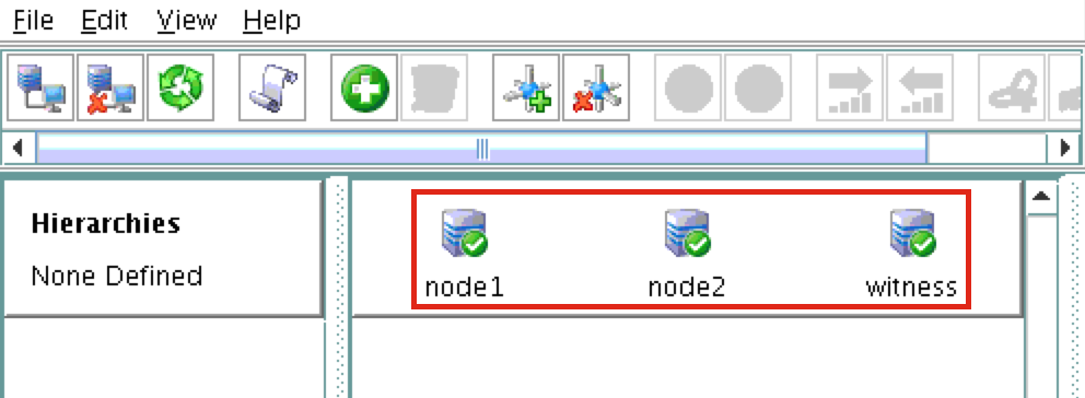
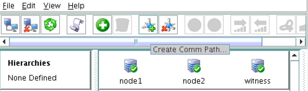
You should now see all 3 servers in the GUI, with a green checkmark icon indicating they are online and healthy:
Create Communication Paths
Right-click on “node1” and select Create Comm Path
Select BOTH “node2” and “witness” and then follow the wizard. This will create comm paths between:
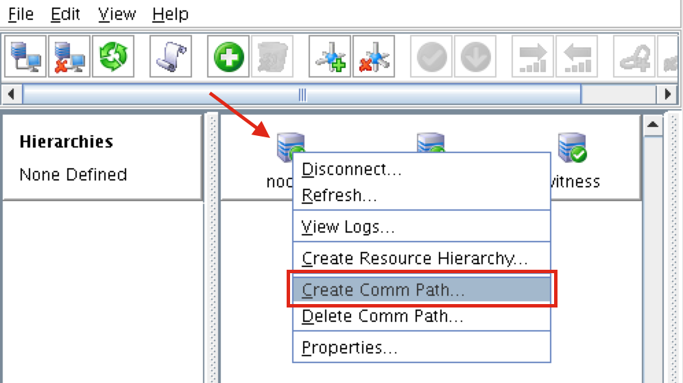
node1 & node2 node1 & witness
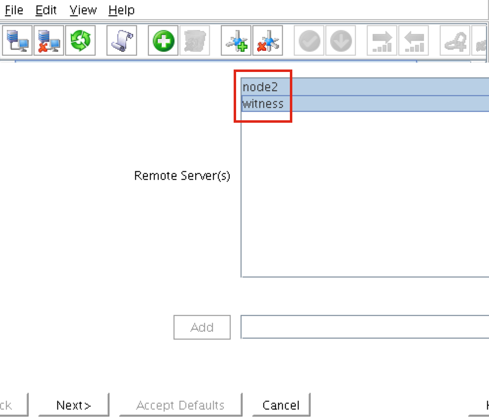
A comm path still needs to be created between node2 & witness. Right click on “node2” and select Create Comm Path. Follow the wizard and select “witness” as the remote server:

At this point the following comm paths have been created:
node1 <—> node2 node1 <—> witness node2 <—> witness
The icons in front of the servers have changed from a green “checkmark” to a yellow “hazard sign”. This is because we only have a single communication path between nodes.
If the VMs had multiple NICs (information on creating Azure VMs with multiple NICs can be found here, but won’t be covered in this article), you would create redundant comm paths between each server.
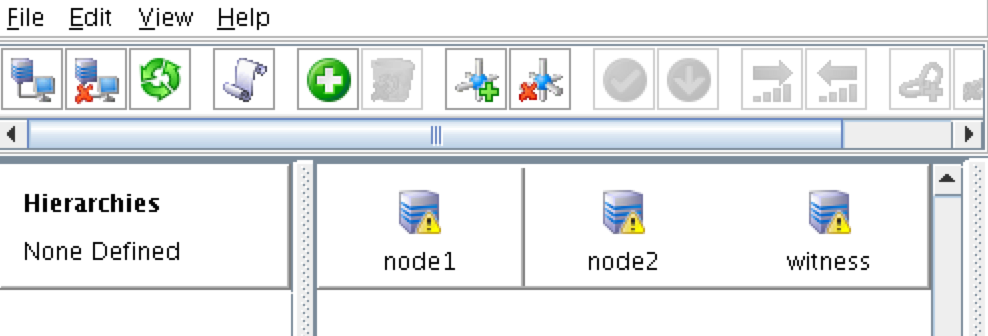
To remove the warning icons, go to the View menu and de-select “Comm Path Redundancy Warning”:
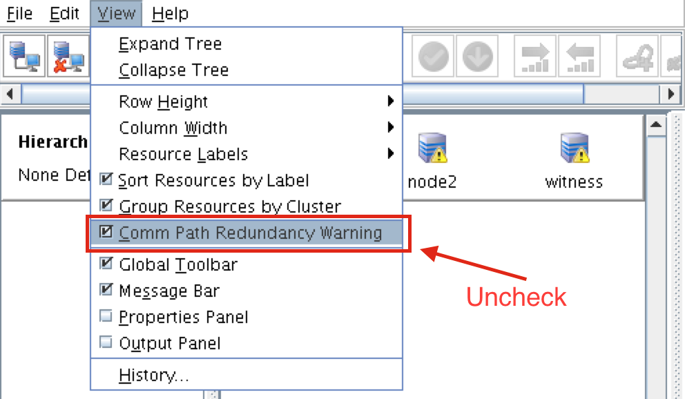
Result:
Verify Communication Paths
Use the “lcdstatus” command to view the state of cluster resources. Run the following commands to verify that you have correctly created comm paths on each node to the other two servers involved:
# /opt/LifeKeeper/bin/lcdstatus -q -d node1
MACHINE NETWORK ADDRESSES/DEVICE STATE PRIO node2 TCP 10.0.0.4/10.0.1.4
ALIVE 1 witness TCP 10.0.0.4/10.0.2.4 ALIVE 1
#/opt/LifeKeeper/bin/lcdstatus -q -d node2
MACHINE NETWORK ADDRESSES/DEVICE STATE PRIO node1 TCP 10.0.1.4/10.0.0.4
ALIVE 1 witness TCP 10.0.1.4/10.0.2.4 ALIVE 1
#/opt/LifeKeeper/bin/lcdstatus -q -d witness
MACHINE NETWORK ADDRESSES/DEVICE STATE PRIO node1 TCP 10.0.2.4/10.0.0.4
ALIVE 1 node2 TCP 10.0.2.4/10.0.1.4 ALIVE 1
Create a Data Replication cluster resource (i.e. Mirror)
Next, create a Data Replication resource to replicate the /var/lib/mysql partition from node1 (source) to node2 (target). Click the “green plus” icon to create a new resource:
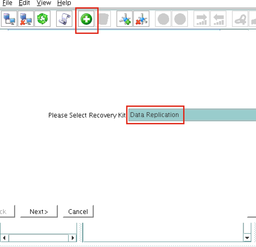
Follow the wizard with these selections:
Please Select Recovery Kit: Data Replication Switchback Type: intelligent
Server: node1
Hierarchy Type: Replicate Exiting Filesystem
Existing Mount Point: /var/lib/mysql
Data Replication Resource Tag: datarep-mysql
File System Resource Tab: /var/lib/mysql
Bitmap File: (default value)
Enable Asynchronous Replication: No
After the resource has been created, the “Extend” (i.e. define backup server) wizard will appear.
Use the following selections:
Target Server: node2 Switchback Type: Intelligent Template Priority: 1
Target Priority: 10 Target Disk: /dev/xvdb1
Data Replication Resource Tag: datarep-mysql Bitmap File: (default value)
Replication Path: 10.0.0.4/10.0.1.4 Mount Point: /var/lib/mysql
Root Tag: /var/lib/mysql
The cluster will look like this:
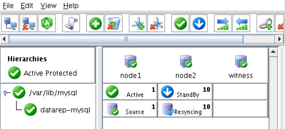
Create Virtual IP
Next, create a Virtual IP cluster resource. Click the “green plus” icon to create a new resource:
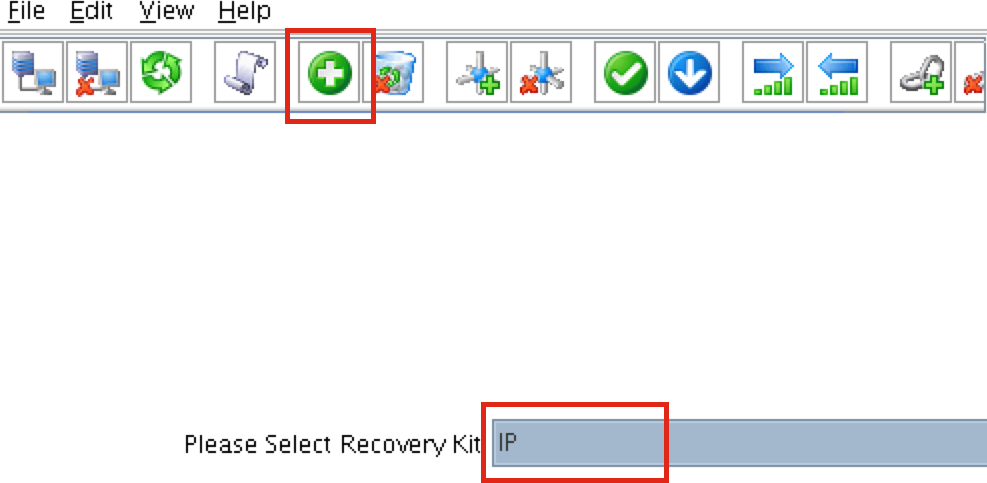
Follow the wizard to create the IP resource with these selections:
Select Recovery Kit: IP Switchback Type: Intelligent IP Resource: 10.1.0.10
Netmask: 255.255.255.0
Network Interface: eth0
IP Resource Tag: ip-10.1.0.10
Extend the IP resource with these selections:
Switchback Type: Intelligent Template Priority: 1
Target Priority: 10
IP Resource: 10.1.0.10
Netmask: 255.255.255.0
Network Interface: eth0
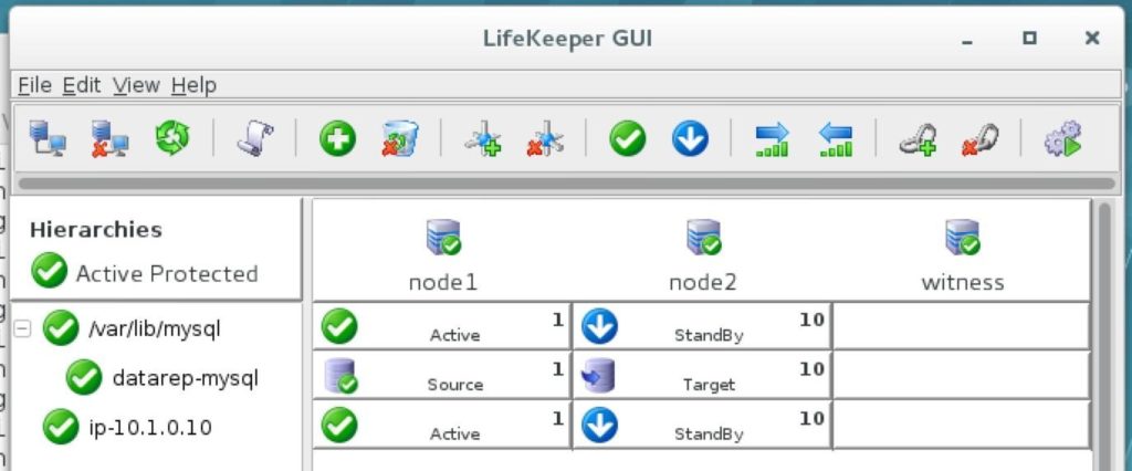
IP Resource Tag: ip-10.1.0.10
The cluster will now look like this, with both Mirror and IP resources created:
Configure a Ping List for the IP resource
By default, SPS-Linux monitors the health of IP resources by performing a broadcast ping. In many virtual and cloud environments, broadcast pings don’t work. In a previous step, we set “NOBCASTPING=1” in
/etc/default/LifeKeeper to turn off broadcast ping checks. Instead, we will define a ping list.
This is a list of IP addresses to be pinged during IP health checks for this IP resource.
In this guide, we will add the witness server (10.0.2.4) to our ping list.
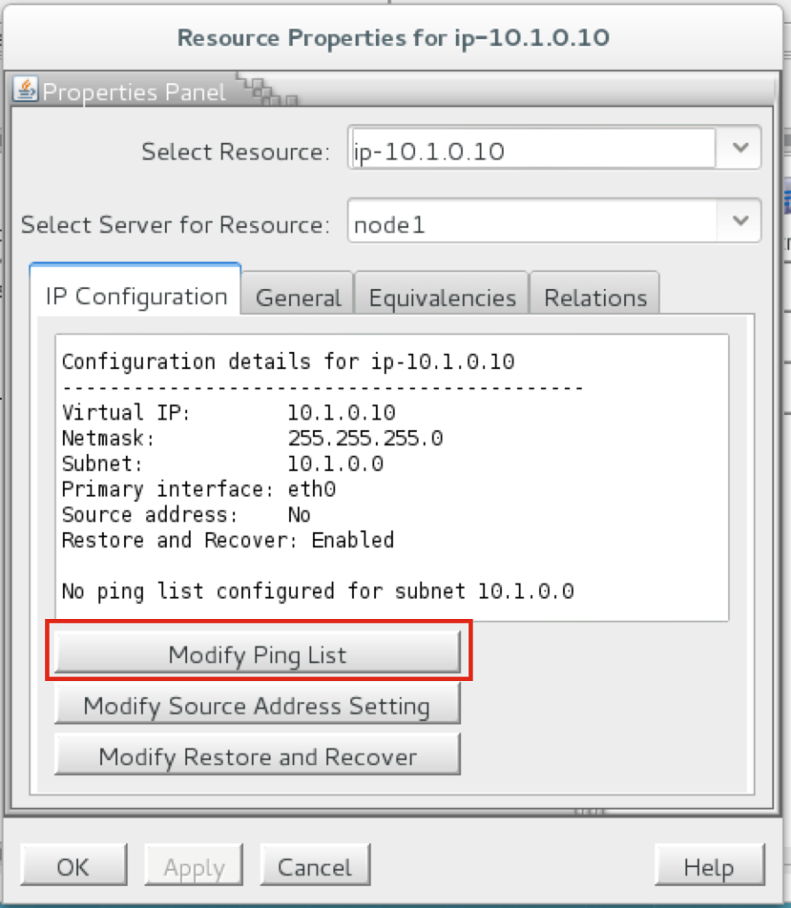
Right-click on the IP resource (ip-10.1.0.10) and select Properties:
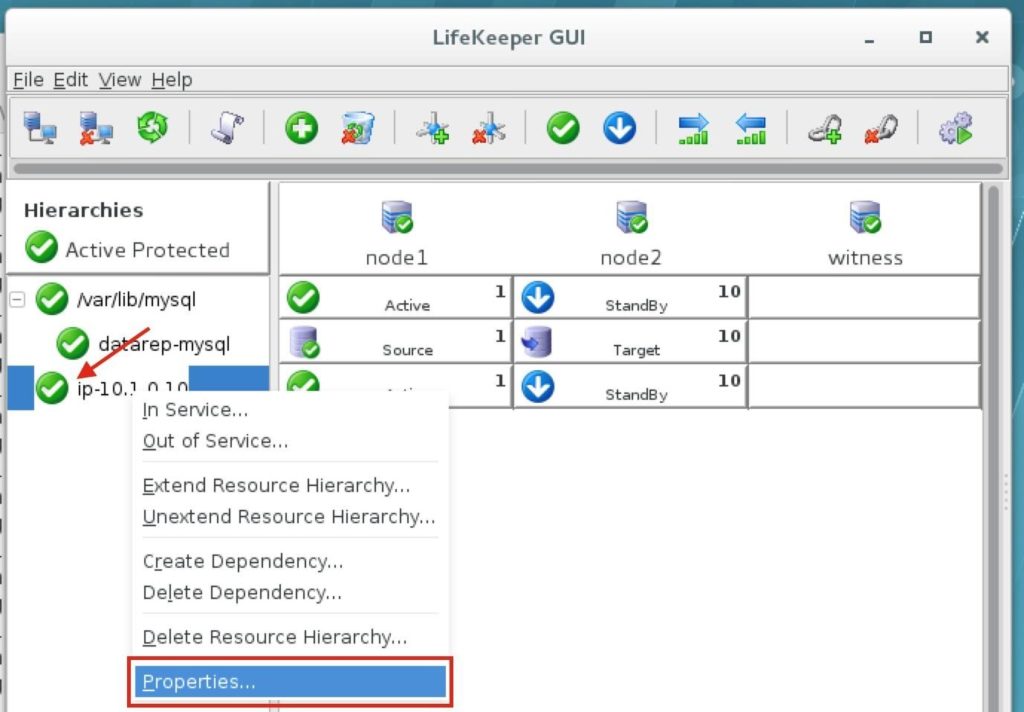
You will see that initially, no ping list is configured for our 10.1.0.0 subnet. Click “Modify Ping List”:
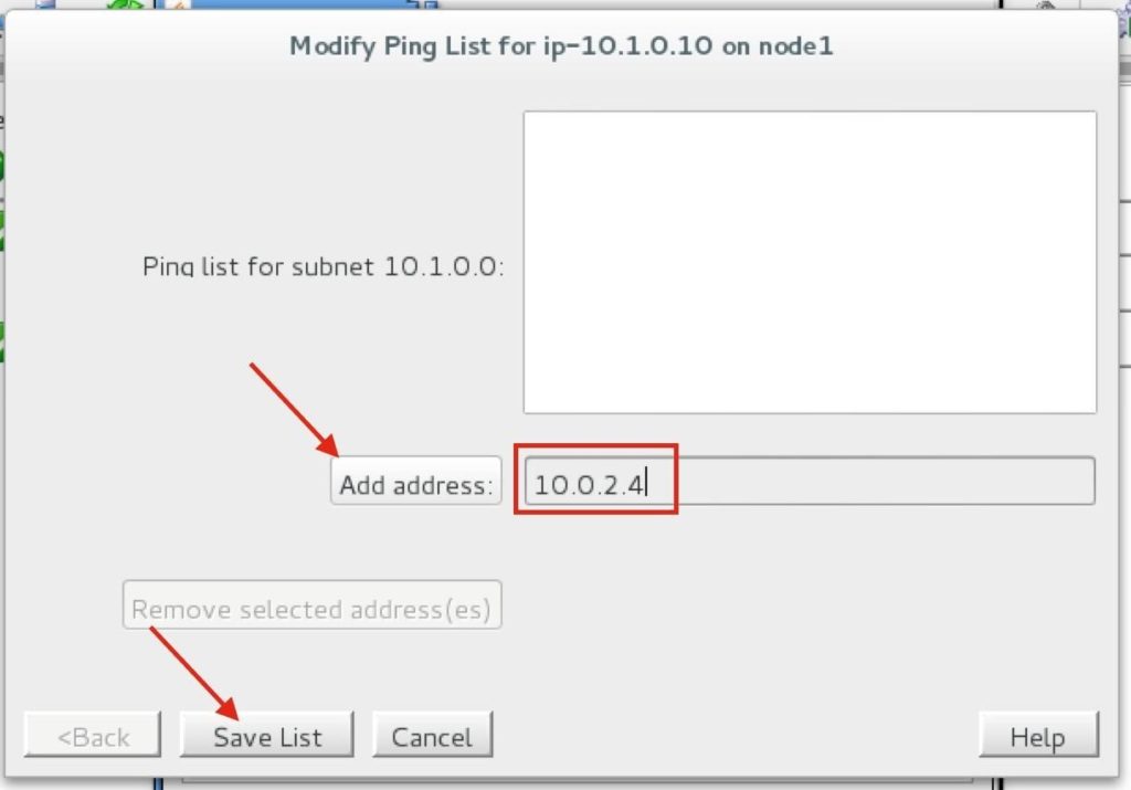
Enter “10.0.2.4” (the IP address of our witness server), click “Add address” and finally click “Save List”:
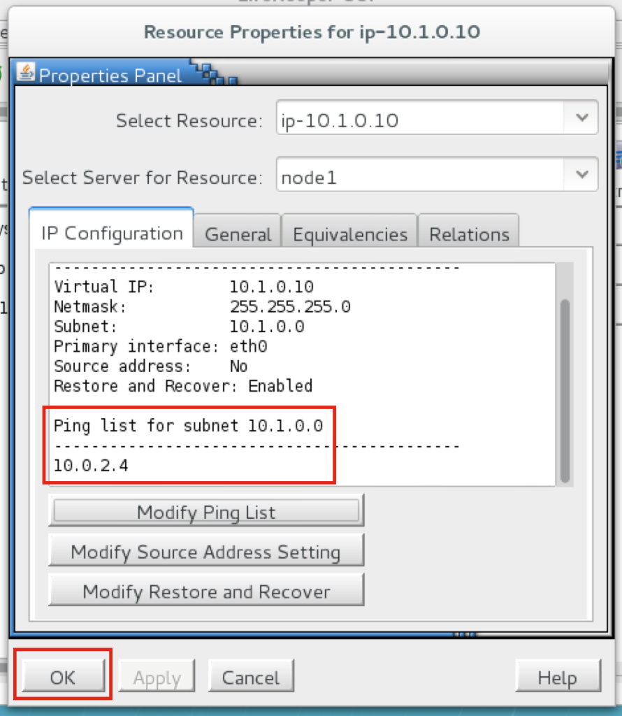
You will be returned to the IP properties panel, and can verify that 10.0.2.4 has been added to the ping list. Click OK to close the window:
Create the MySQL resource hierarchy
Next, create a MySQL cluster resource. The MySQL resource is responsible for stopping/starting/monitoring of your MySQL database.
Before creating MySQL resource, make sure the database is running. Run “ps -ef | grep sql” to check.
If it’s running, great – nothing to do. If not, start the database back up:
# mysqld_safe –user=root –socket=/var/lib/mysql/mysql.sock –port=3306 –datadi
Follow the wizard with to create the IP resource with these selections:To create, click the “green plus” icon to create a new resource:
Select Recovery Kit: MySQL Database Switchback Type: Intelligent Server: node1
Location of my.cnf: /var/lib/mysql
Location of MySQL executables: /usr/bin
Database Tag: mysql
Extend the IP resource with the following selections:
Target Server: node2 Switchback Type: intelligent Template Priority: 1
Target Priority: 10
As a result, your cluster will look as follows. Notice that the Data Replication resource was automatically moved underneath the database (dependency automatically created) to ensure it’s always brought online before the database:
Create an EC2 resource to manage the route tables upon failover
SPS-Linux provides specific features that allow resources to failover between nodes in different availability zones and regions. Here, the EC2 Recovery Kit (i.e. cluster agent) is used to manipulate Route Tables so that connections to the Virtual IP are routed to the active cluster node.
To create, click the “green plus” icon to create a new resource:
Follow the wizard to create the EC2 resource with these selections:
Select Recovery Kit: Amazon EC2 Switchback Type: Intelligent Server: node1
EC2 Home: /opt/aws
EC2 URL: ec2.us-west-2.amazonaws.com
AWS Access Key: (enter Access Key obtained earlier) AWS Secret Key: (enter Secret Key obtained earlier) EC2 Resource Type: RouteTable (Backend cluster)
IP Resource: ip-10.1.0.10
EC2 Resource Tag: ec2-10.1.0.10
Extend the IP resource with the following selections:
Target Server: node2 Switchback Type: intelligent Template Priority: 1
Target Priority: 10
EC2 Resource Tag: ec2-10.1.0.10
The cluster will look like this. Notice how the EC2 resource is underneath the IP resource:
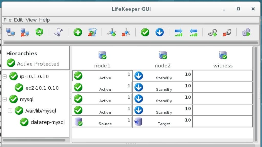
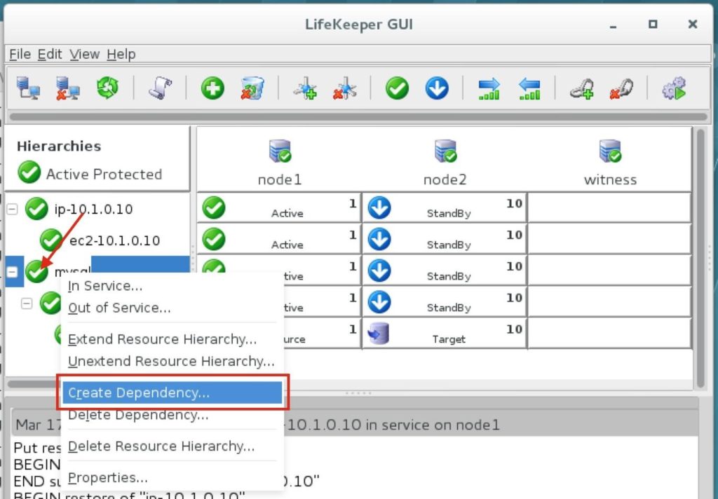
Create a Dependency between the IP resource and the MySQL Database resource
Create a dependency between the IP resource and the MySQL Database resource so that they failover together as a group. Right click on the “mysql” resource and select “Create Dependency”:
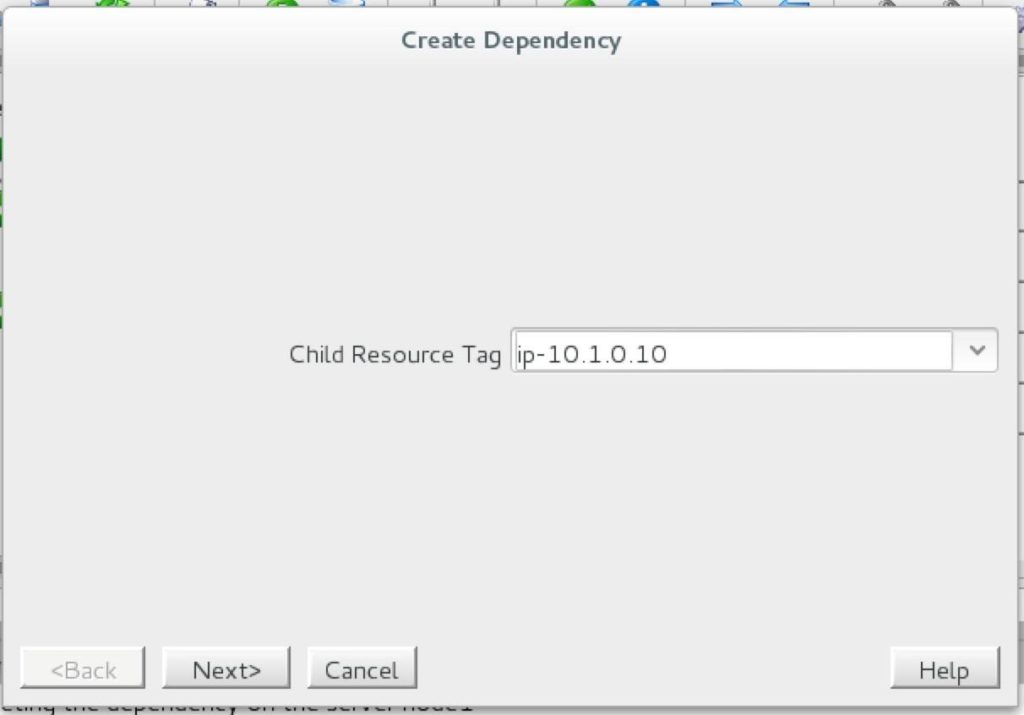
On the following screen, select the “ip-10.1.0.10” resource as the dependency. Click Next and continue through the wizard:
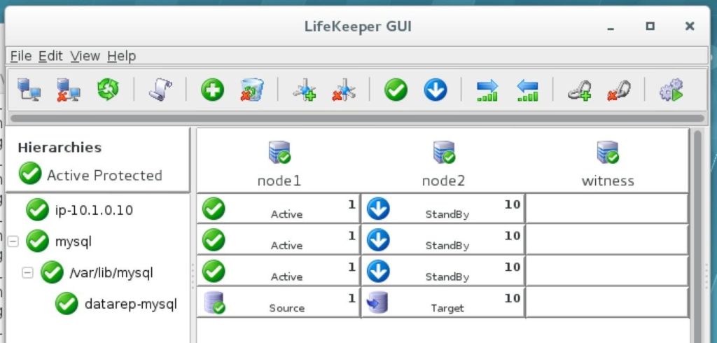
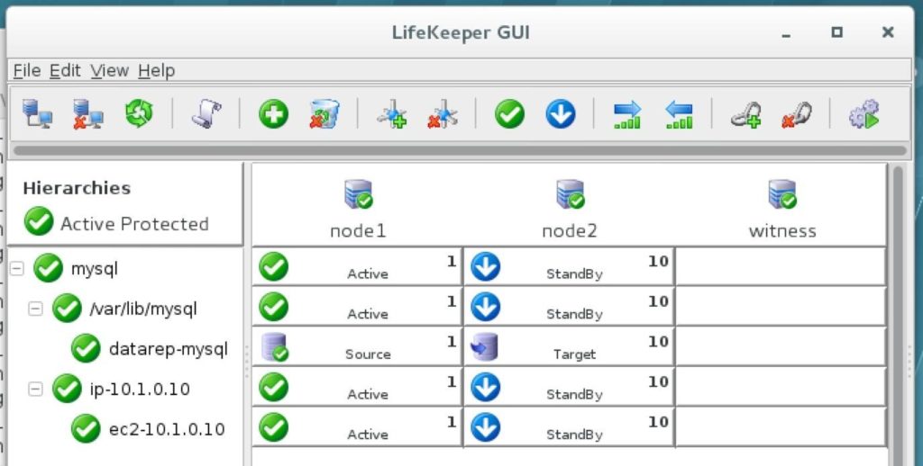
At this point the SPS-Linux cluster configuration is complete. The resource hierarchy will look as follows:

Step 15: Test Cluster Connectivity
At this point, all of our Amazon EC2 and Cluster configurations are complete! Cluster resources are currently active on node1:
Test connectivity to the cluster from the witness server (or another linux instance if you have one) SSH into the witness server, “sudo su -” to gain root access. Install the mysql client if needed:
[root@witness ~]# yum -y install mysql
Test MySQL connectivity to the cluster:
[root@witness ~]# mysql –host=10.1.0.10 mysql -u root -p
Execute the following MySQL query to display the hostname of the active cluster node:
MariaDB [mysql]> select @@hostname;
++
| @@hostname |
++
| node1 |
++
1 row in set (0.00 sec) MariaDB [mysql]>
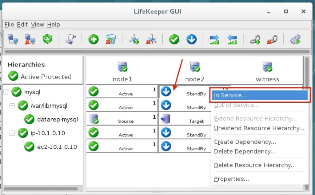
Using LifeKeeper GUI, failover from Node1 -> Node2″. Right-click on the mysql resource underneath node2, and select “In Service…”:
After failover has completed, re-run the MySQL query. You’ll notice that the MySQL client has detected that the session was lost (during failover) and automatically reconnects:
Execute the following MySQL query to display the hostname of the active cluster node, verifying that now “node2” is active:
MariaDB [mysql]> select @@hostname;
ERROR 2006 (HY000): MySQL server has gone away No connection. Trying to reconnect…
Connection id: 12
Current database: mysql
++
| @@hostname |
++
| node2 |
++
1 row in set (0.53 sec) MariaDB [mysql]>
Reproduced with permission from SIOS


 Connect to SQL1